
boejoula
Well-Known Member
- 215
- 68
- Vehicle Model
- Civic Si
- Body Style
- Sedan
This si my first DIY so i apologize ahead of time!
You will need to purchase:
An external switch
A relay
Blue male spade
Yellow T-Tap
15AMP Fuse
First thing you want to do it locate the factory fog light relay. It is under the hood, on the right side of the engine bay.
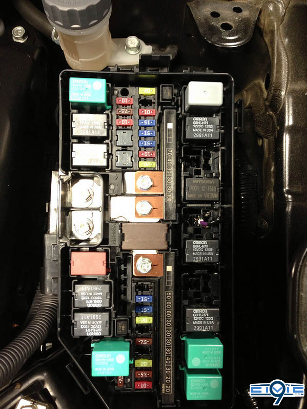
On the right side of the fuse box you will see the relays. You want the 5th fuse from the top, pull it out (to double check this is the correct fuse turn the fogs on and make sure they dont come on). Your going to use a male spade connector without the plastic to plug into where the power was fed by the factory relay. I used a 16 gauge wire.
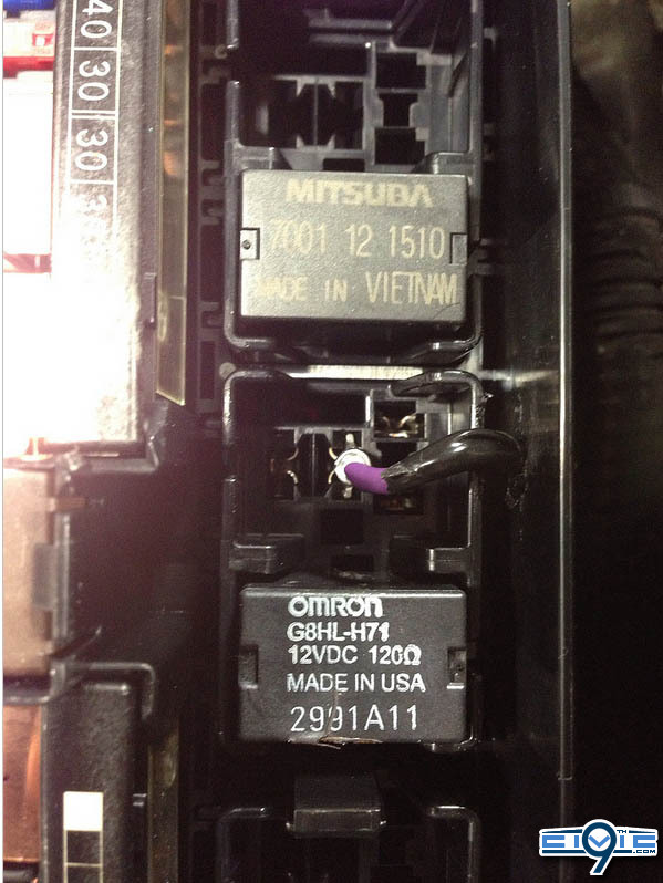
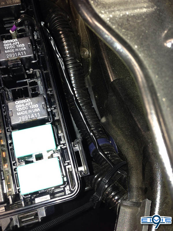
Drill a hole just big enough for the wire to fit on the side of the fuse box and feed the wire through. Your going to run this along the loomed wires on the outside of the fuse box towards the headlight.
You want to go under the rad support and into the fender. Here's where you want to take the fender liner out/down on the right side of the wheel well. Refer to http://9thcivic.com/forum/threads/resonator-delete-si-sedan.4811/ for pics of the wheel well liner (THANKS@smokedditty) YOU WILL BE REMOVING THE 3 PIECES HE HAS MARKED WITH AN X
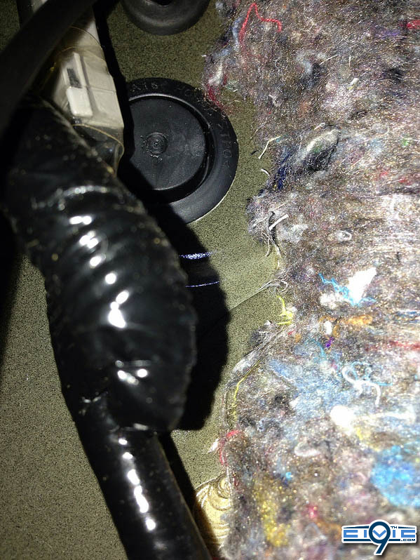
Once you get the liner out of the way, lightly wire tie the new fog light wire to the hood latch so it doesn't dangle. Right under the gromet for the hood latch is an empty gromet the you will drill a small hole through to get your wire into the car
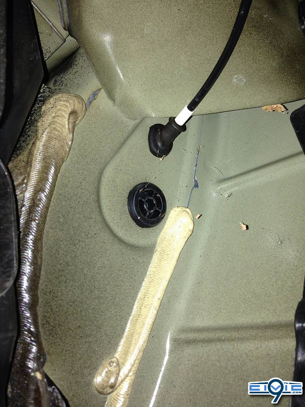
This is the other side of the gromet, again, right below thr hood latch cable.
Now your going to want to get the switch and relay.
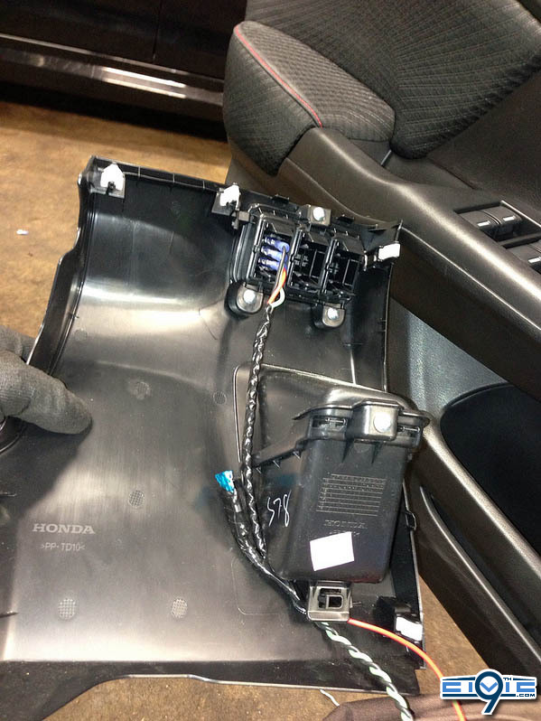
First, remove the under dash panel
http://www.collegehillshonda.com/instructions/civic/2012/4dr/ambientlightsi.pdf page 3
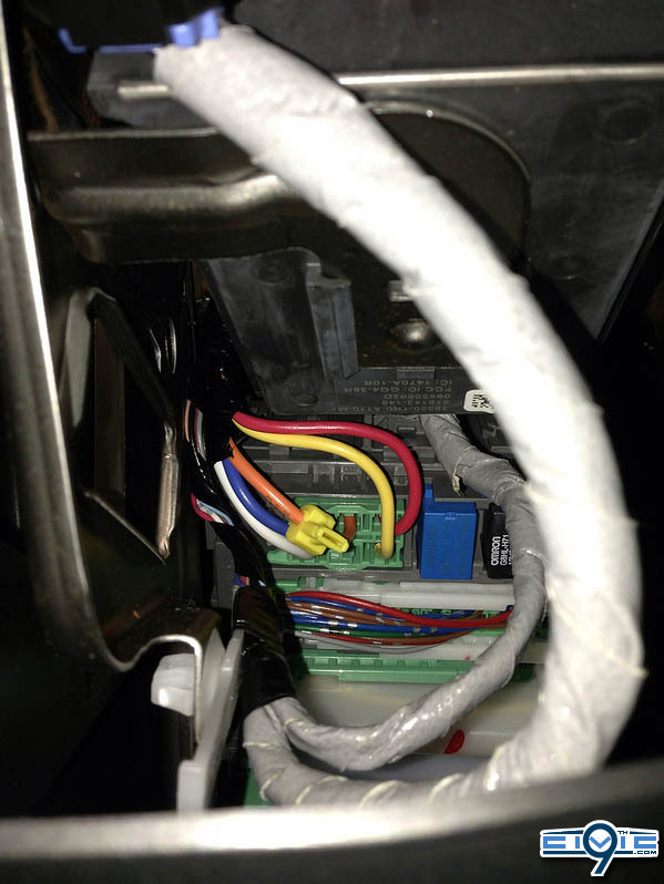
T-tap the main ignotion wire. It is the orange wire at the top of the interior fuse box
Wire up the switch depending on what type of switch you have. My switch looks like this:
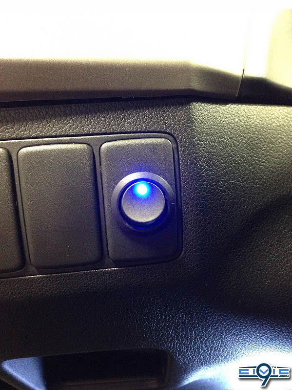
And the wiring (leave a little slack on the wire for reinstalling the panel):
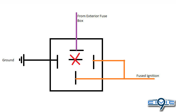
This is the wiring diagram for the relay
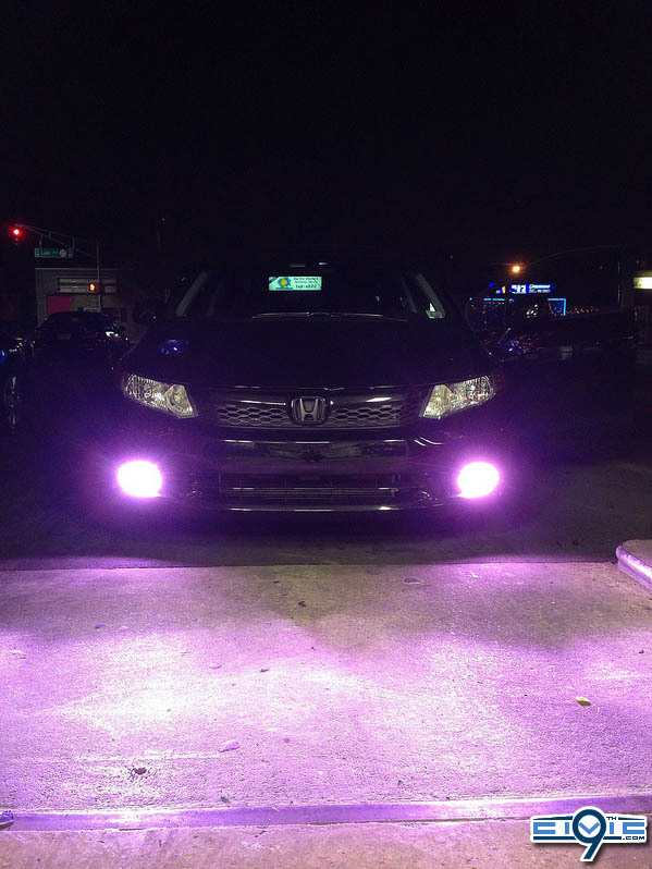
Once its all wired up, connect your new fuse and test these bad boys
Not sure how to do this on models without factory fogs but i would imagine it to be the same.
Any more questions, ask them here or send me a PM. happy to finally give something back to the community!
webby i hope this is up to par for the DIY. Enter me into the next contest please!!
You will need to purchase:
An external switch
A relay
Blue male spade
Yellow T-Tap
15AMP Fuse
First thing you want to do it locate the factory fog light relay. It is under the hood, on the right side of the engine bay.
On the right side of the fuse box you will see the relays. You want the 5th fuse from the top, pull it out (to double check this is the correct fuse turn the fogs on and make sure they dont come on). Your going to use a male spade connector without the plastic to plug into where the power was fed by the factory relay. I used a 16 gauge wire.
Drill a hole just big enough for the wire to fit on the side of the fuse box and feed the wire through. Your going to run this along the loomed wires on the outside of the fuse box towards the headlight.
You want to go under the rad support and into the fender. Here's where you want to take the fender liner out/down on the right side of the wheel well. Refer to http://9thcivic.com/forum/threads/resonator-delete-si-sedan.4811/ for pics of the wheel well liner (THANKS@smokedditty) YOU WILL BE REMOVING THE 3 PIECES HE HAS MARKED WITH AN X
Once you get the liner out of the way, lightly wire tie the new fog light wire to the hood latch so it doesn't dangle. Right under the gromet for the hood latch is an empty gromet the you will drill a small hole through to get your wire into the car
This is the other side of the gromet, again, right below thr hood latch cable.
Now your going to want to get the switch and relay.
First, remove the under dash panel
http://www.collegehillshonda.com/instructions/civic/2012/4dr/ambientlightsi.pdf page 3
T-tap the main ignotion wire. It is the orange wire at the top of the interior fuse box
Wire up the switch depending on what type of switch you have. My switch looks like this:
And the wiring (leave a little slack on the wire for reinstalling the panel):
This is the wiring diagram for the relay
Once its all wired up, connect your new fuse and test these bad boys
Not sure how to do this on models without factory fogs but i would imagine it to be the same.
Any more questions, ask them here or send me a PM. happy to finally give something back to the community!
webby i hope this is up to par for the DIY. Enter me into the next contest please!!


