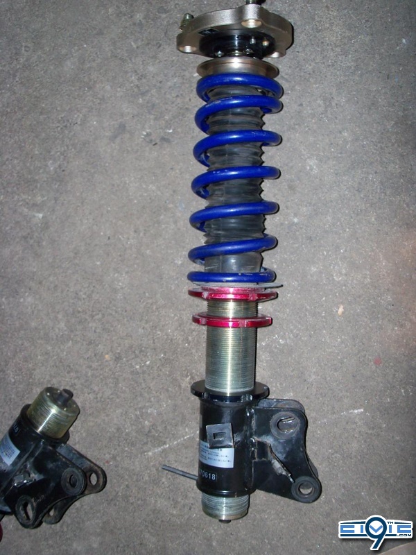
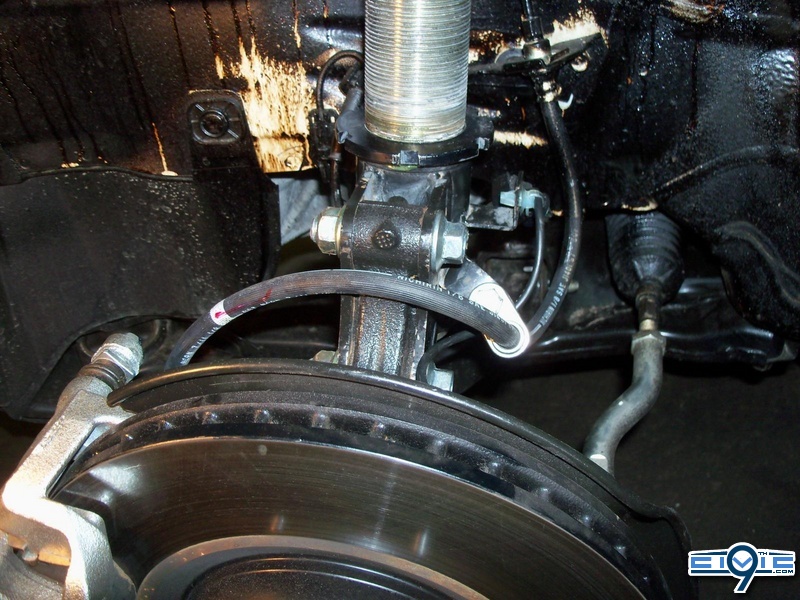
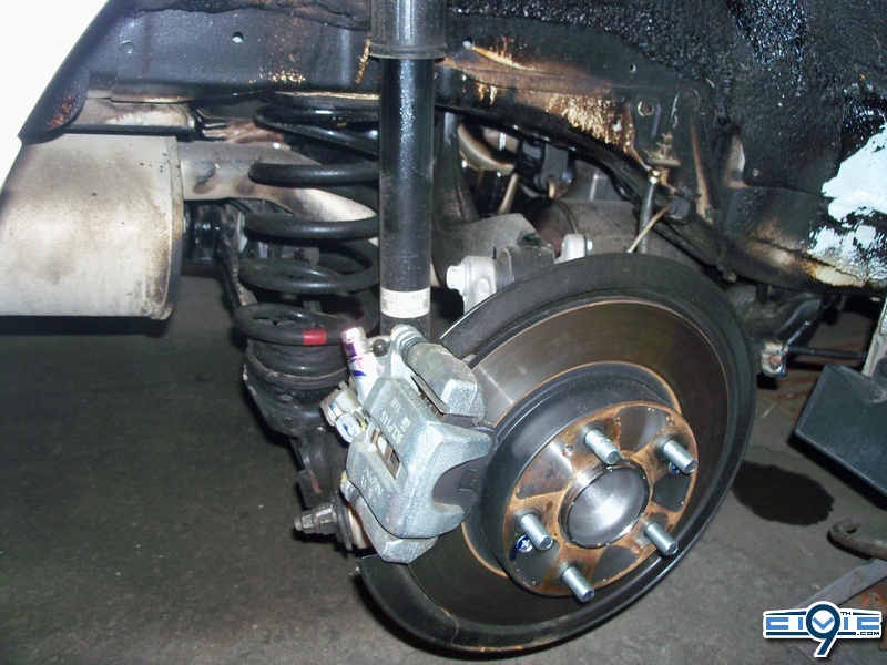
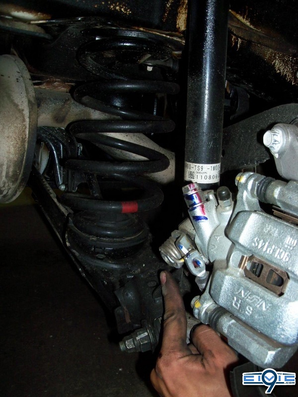
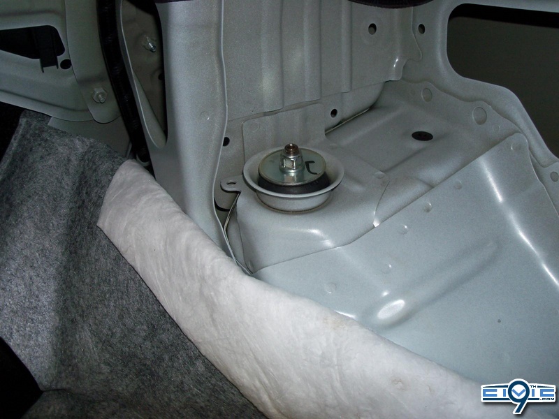
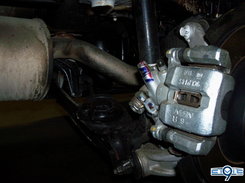
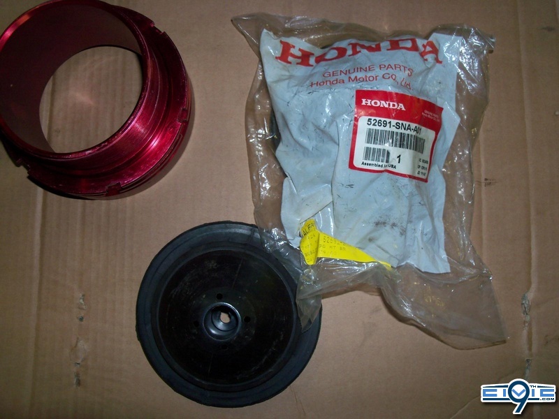
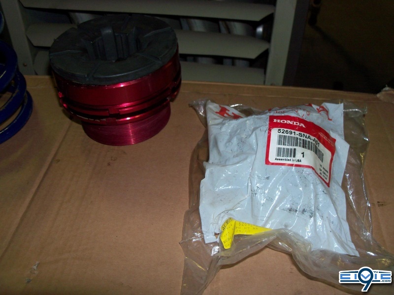
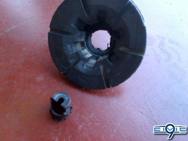
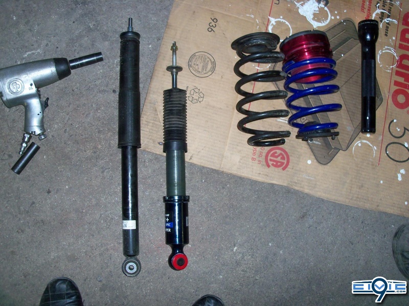
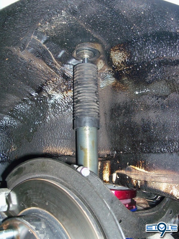
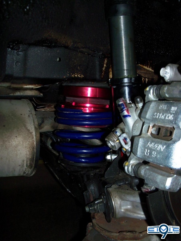
hello everyone, before *attempting* this DIY (at your own risk) you must have already completely the http://9thcivic.com/forum/threads/diy-2012-civic-front-sway-bar-removal-warning-picture-heavy.4757 DIY: Front Sway Bar Removal - (warning picture heavy) “. The reason for removing the front sway bar is that 8th generation civics did not come with a factory front sway bar, therefore the suspension from an 8th gen will not have the mounting brackets for the end links (which would connect the OEM shock to the actual sway bar). Once the front sway bar removal is complete, the coilover installation is pretty straight forward if you’ve done it before. If you have never installed coilovers before it is much easier then installing lowering springs, which would involve the use of a spring compressor to fit your new lowering springs onto your OEM shock assembly.
Disclaimer - Please read this, it saves my *** from any trouble and explains the context of the DIY
This is a step by step process on how I successfully installed 8th generation coilovers on a 9th gen civic. This “DIY” (do-it-yourself) is a detailed explanation on how I did it, MYSELF.
I do not take any responsibility for potential actions performed due to this write up. If you decide that you have learned enough, have enough experience, and have the proper tools to do this install…..your are doing so at YOUR OWN RISK. This DIY will be written in first person (as myself) or in the third person (One must, one may, one should…..). Sometimes I will say “you can, try this…, get someone to, etc.” but that will only be for basic tasks, tasks that I know you cannot screw up on or break anything if you *attempt this DIY* at your own risk.
Pre- DIY **Notes** (Including safety) - PLEASE READ ALL before starting:
- When using jack stands, always insure the car is on a levelled flat surface. At times, one may be working underneath the car, within the trunk compartment and within the wheel well area. It is very important that the car is levelled because I have personally witnessed a car being dropped on the floor. All it takes is a little push or force (will be using a crow bar in this DIY) + uneven work space for a cars weight distribution to instantly be transferred and a scary unsafe situation arises….
- When removing the front coils and rear springs, one MUST use a jack to support the lower control arm.
-If the car has a locking lug nut set, please retrieve the locking nut key in the glove box and/or trunk prior to starting any steps.
- The car should be parked in an area with good lighting and possibly some cover just in case of bad weather (if work is done outside)
- Before jacking up the car (with the key in the ignition), roll down both front windows, fully open sunroof, open trunk and pop the hood. Later in the DIY, it is necessary to place the key in the accessory position (to unlock steering wheel) and turn the steering wheel all the way to the left/right. If you remove the key, you might have to open the door and step back into the car to find the slot. I would advise to keep the key in the ignition, but not on accessory that way you don’t kill the battery.
(While completing the installation, the car will either be on a hoist or on 4 jack stands. One should never enter a car while on a hydraulic hoist OR jack stands for obvious safety reasons. By popping the hood, opening the trunk and rolling down the front windows AT THE START….one will have access to the entire car without ever opening up a door. )
- Turn off the car, apply the emergency hand brake and put the car into gear.
DIY: 8thgen coilovers Installed on 9thgen Civic SI
Step 1. Start off by going into your glove box and retrieving your owner’s manual. Search through your manual and locate the designated jacking points. On the side of the car (where the side skirts are normally located) you will find the 2 jacking points. The rear jack point is about 1 foot before the rear wheel well and the front jack point is about ½ foot after the front wheel well. You may be able to use the tow hooks as a jacking point (explained bellow) but you still need to learn the location of the side frame jacking points because that is where you will be placing your jack stands….
**Side note about using tow hooks for jack points:
One can always jack up their car using the tow hooks, but depending on what kind of jack stands and floor jack you are using, this may not raise the car up enough to slide the jack stands underneath the side of the car. Looking at the front of the car (laying on the floor obviously) you will be able to see the two front tow hooks. They are located just in front of the wheels and slightly towards the center of the car. They are simply a looped black metal bar about 1.5-2” big. You can place your jack on each of these two tow hooks to lift up each side of the car one at a time. The rear tow hook location is obvious; it’s underneath the rear bumper directly in the middle of the car (and should be in plain view). Since the front has two tow hooks that are located more towards the wheel and the side of the car, when jacking up from those points the side of the car is able to lift up to a good height. Now, since the rear tow hook is placed in the middle of the rear and farther away from the side frame rails, when jacking up from the rear you will most likely not achieve the height necessary to slide the jacks underneath the rear side of the car.
I found a picture of the big jack (it’s actually huge) and it’s on the front drivers side tow hook.
I did not use the tow hook as jack points, I just forgot that I took this picture to show people.
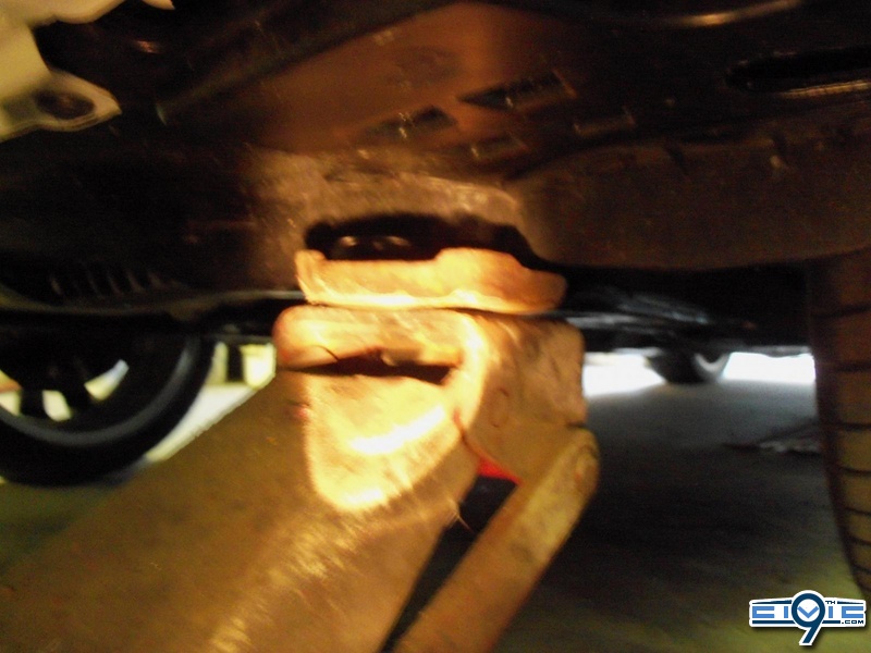
Step 2. Now, actually jack up the car (however you choose) and place the 4 jack stands in the location shown in the manual as the jacking points.
I decided to use monster truck jacks (just kidding) because it gave me more space to work under and around the car.
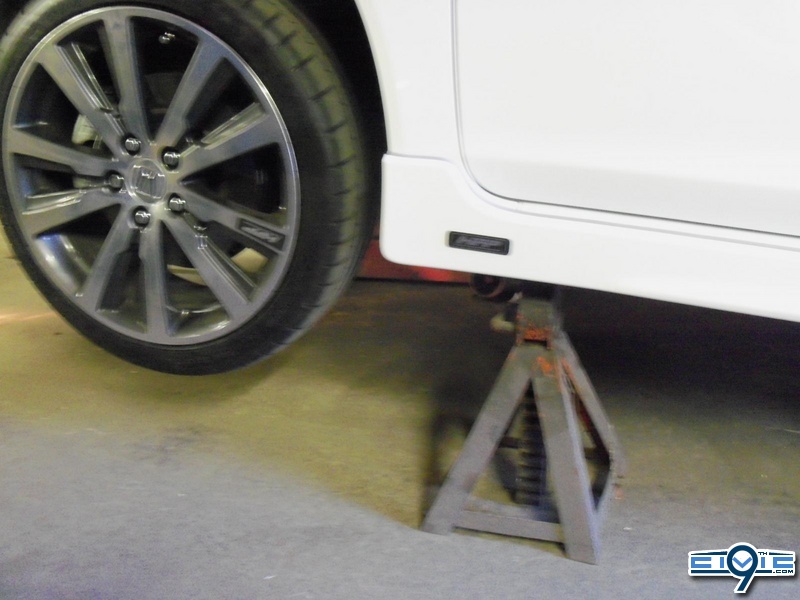
Step 3. Use a 19mm socket to remove your lugs nuts from your wheels. The rear wheels should not move and should be locked up, this is because your applied the emergency hand brake. The front wheels will start to spin when you go to remove your lug nuts. I have a very detailed explanation about tranny lock and how to remove your front lugs successfully in my “ DIY: Front Sway Bar Removal - (warning picture heavy) “ thread. Basically, when you spin one of your wheels towards the front of the car, the other wheel will travel in the opposite direction towards the back of the car (this is the tranny lock when our 9th’s are in gear). Either ask someone to assist you and hold onto the rim while you loosen/break the lug nuts free, or just try and do it yourself.
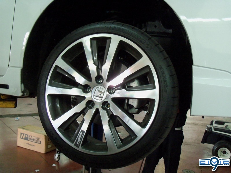
Step 4. Once all of lugs nuts have been removed, you can remove the wheel and place it off to the side. Do this for all 4 wheels at the same time
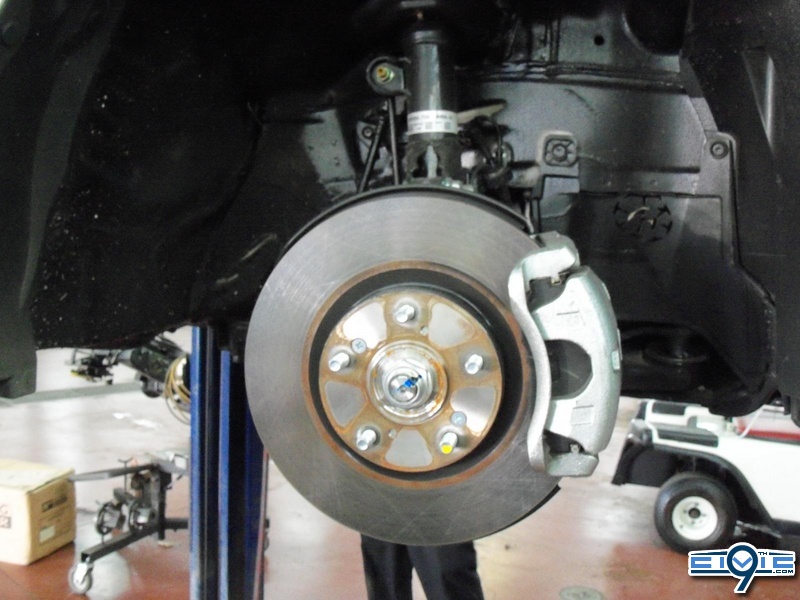
Step 5. Now that the car is on a hoist or 4 jack stands and we have removed the wheels, you can begin to dismantle the plastic wiper housing. This will allow access to the 3 bolts that are securing the front coilover in place.
Begin by removing the rounded plastic cap on the start of the wiper arm. I don’t have pictures of this round cap, but you simply use a flat head screw driver and lift it off. Once removed, it will reveal one nut that holds the wiper arm in place. (Same procedure for the other side)
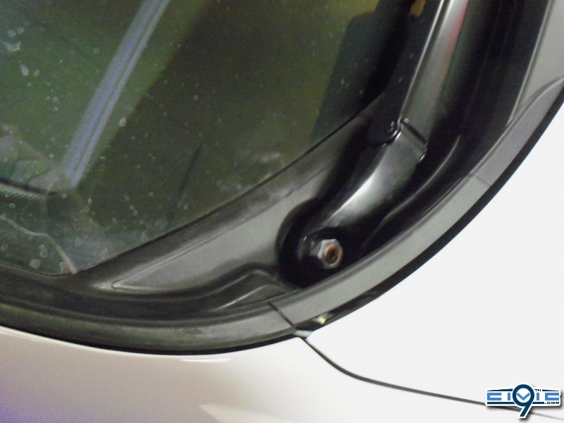
Step 6. BEFORE removing the nut, either take a picture of the wiper position or mark the glass with a piece of tape. The bolt that the wiper arm sits around is similar to a gear. The wiper sits at a certain resting position and once you apply the wiper switch the gear rotates and moves the wiper. When you go back and install your wiper, you won’t know how far up or down the regular position was unless you looking at another 9th gen civic.
It would also be a good idea to note which wiper arm was left and which arm was right. It saves some time figuring things out when you start to wrap up your install. (Same procedure for the other side)
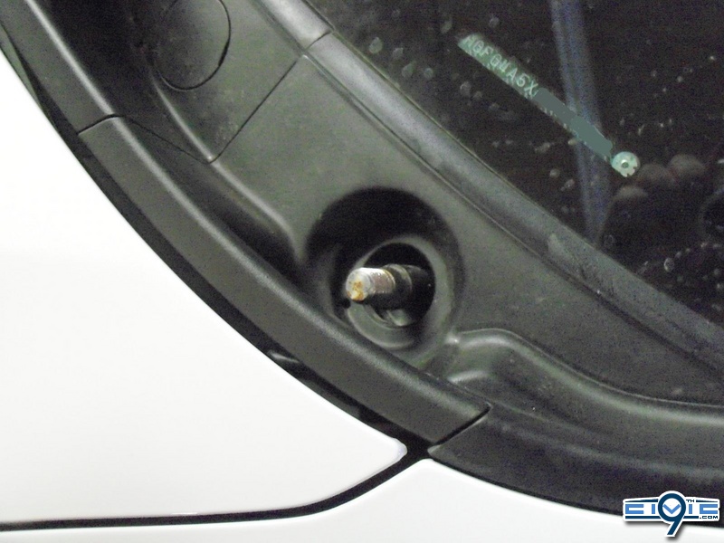
Step 7. I would recommend threading the wiper nut back onto the bolt, just because it won’t get misplaced later on. Now we need to remove that flat round plastic cap. If you look closely there is a small opening for a flat head screw driver to tuck inside. Do not attempt to pry it off from one of the clean edges (you will scratch, bend and possibly crack this piece. It’s also $5 to replace from Honda). Using the proper sized flat head and a little bit of pressure, pop the flat plastic piece up and out.
(Same procedure for the other side)
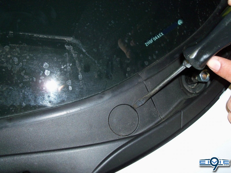
Step 8. At this point, you hood should have been already popped (from the Pre-DIY) but not open. Now open your hood and locate the plastic trim piece that runs along the side of your fender. This piece goes from the washer fluid container area, all the way along the side the fender and up to the plastic cowl we are trying to remove. At the top of the ‘side’ plastic, there is a plastic push clip that secures it and the cowl to the car. We need to remove this clip in order to free the cowl and allows us to have more room when working is such a tight area. There are “special” tools we use a Honda to remove these clips and it definitely comes in handy if you own one. If not, then you can simply use a small flat head screw driver, or a mini pick. ( Same procedure on both sides)
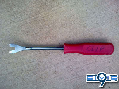
Here is the tool im referring to. It slide right underneath the plastic clip and provides even pressure all the way around the lift the clip out of place. With a screw driver or pick, you might break some of those plastic clips but it very common and always happens.
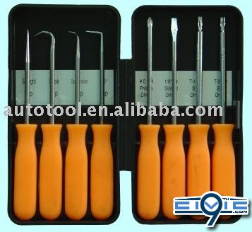
The third and fourth one work the best if you do not have the clip removing tool ^^
Here is after the plastic clip removed
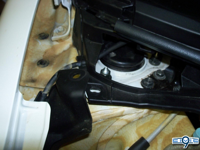
Step 9. In this step one of the pictures turned out really bad so I decided to delete it. It was the picture of the piece you need to remove….i only got a decent picture on the location where it was removed from.
It’s a rectangular piece that sits directly to the right of the wiper nut (in terms of the picture). It held on by little plastic clips and it’s very easy to remove. Just grab the piece and give it a little tug, it should just pull right off. ( Same procedure on both sides)
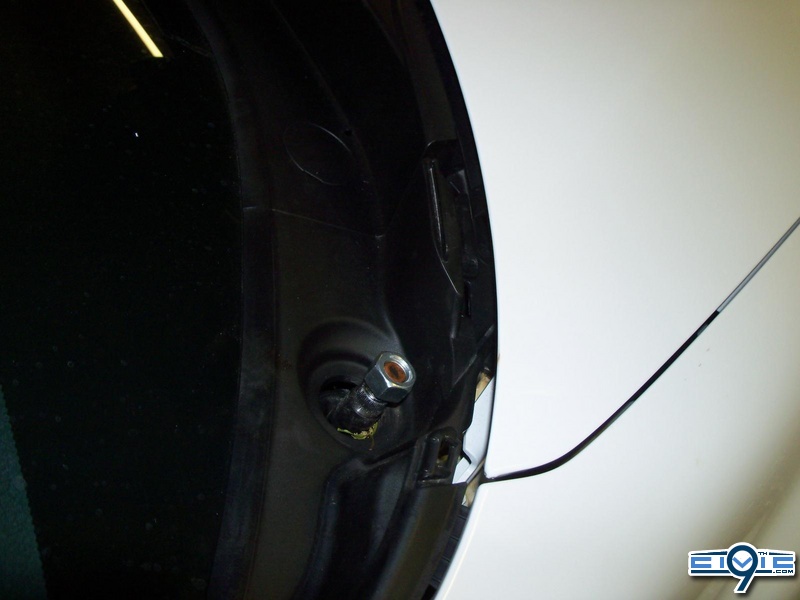
Step 10. . The curved plastic piece that sits on top of the wiper nut area must be removed. Again, this is very simple. This piece doesn’t have any plastic clips that get removed or securely ‘click’ into anything, it just has several pieces of rectangular plastic that tucks into the pillar and into the other side of the plastic cowl.
Begin by grabbing the plastic portion that is closest to the fender. You can see in the picture it is held together by two rectangular tabs. Push the plastic cowl towards the center of the car (DO NOT pull it directly up) and it should unclip fairly easy. ( Same procedure on both sides)
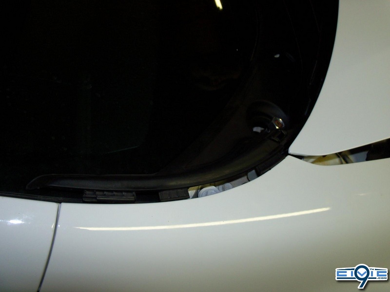
Step 11. Once the push the plastic cowl towards the center of the car, it should look like the picture above ^^^. The other side of this plastic piece is just tabs also, and once you’ve unclipped the fender side, you can simply lift the plastic cowl out. ( Same on both sides)
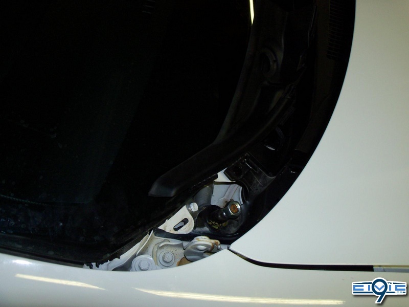
Here is a better view from the top…
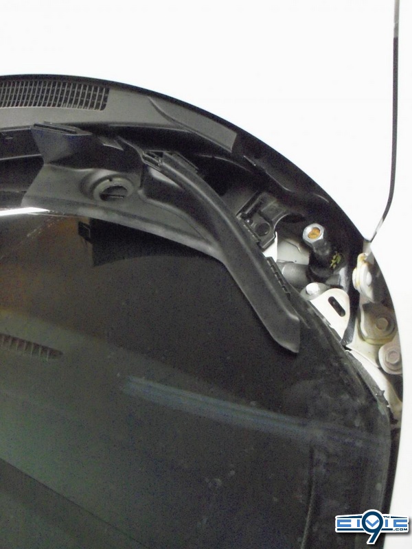
Step 12. The main purpose of removing the plastic cowl pieces is to gain access to the nuts that hold the front coilovers in place. One of the three coilover nuts is picture below. It is located directly down and to the left of the wiper gear and nut.
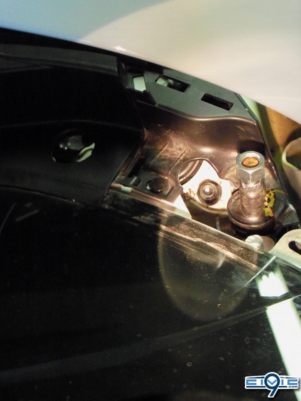
Step 13. The second nut for the coilover is located directly down the circle hole in the cowl. Early one of the steps was to remove this round flat plastic piece with a screw driver.
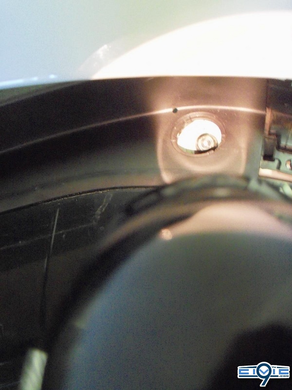
Step 14 . The last and final (3rd) nut that hold the front coilover is located in plain view. If you go back to step 8, we removed that clip that held on the ‘side’ plastic piece to the regular plastic cowl. The last and final nut is located directly behind that area.
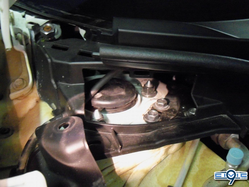
Step 15. At this stage, the process of removing the OEM suspension and installing the 8th gen coils actually begin. As stated in the disclaimer, am I not responsible for any actions performed whether directly stated or implied due to this ‘DIY’. From this step forward i will only speak in first person (as myself) or in third person (one may, one should, one could). I will not state (you should, your* car, etc.)
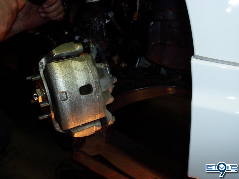
- step 15. When viewing the wheel well area, the end links should not be present. They were removed in my “DIY: Front Sway Bar Removal – (warning picture heavy) “ . All that is left in order to remove the front OEM shock assembly is the 3 nuts at the top of the coil (which mount through the body and are located under the plastic cowl) and 2 large strut bolts, located behind the rotor area.
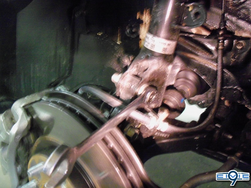
During the actual removal of the 2 strut bolts I used an air impact gun. For the purpose of taking pictures and showing the location of the bolts I used a wrench for demonstration. The wrench is on the upper strut bolt and the second strut bolt is located about 3 inches directly down.
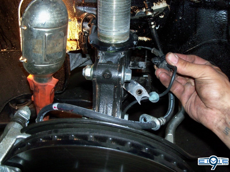
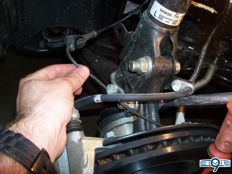
Step 16. One must remove the small plastic clip that holds the ABS line to the OEM shock. It is very important that one pays close attention to not damage, kink or tug on the ABS line….it is sensitive.
One can use their fingers or needle nose pliers (carefully) to squeeze the inside tabs of the ABS clip in order to let it slide out of the mount bracket. It is also important to not damage this clip because it is re-used to clip in the ABS line to the 8th gen coilovers.
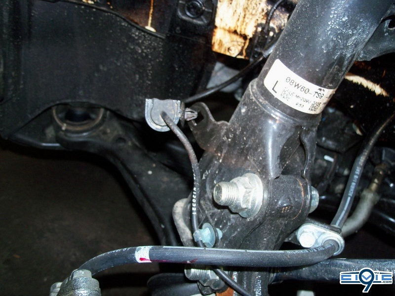
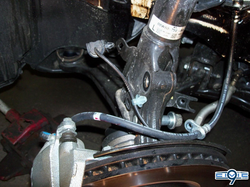
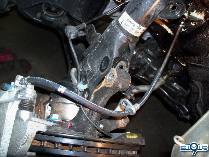
Here’s a nice picture of the ABS click removed, the ABS clip bracket that one must reach behind to squeeze the 2 plastic tabs and the 2 large strut bolts that need to be removed
Disclaimer - Please read this, it saves my *** from any trouble and explains the context of the DIY
This is a step by step process on how I successfully installed 8th generation coilovers on a 9th gen civic. This “DIY” (do-it-yourself) is a detailed explanation on how I did it, MYSELF.
I do not take any responsibility for potential actions performed due to this write up. If you decide that you have learned enough, have enough experience, and have the proper tools to do this install…..your are doing so at YOUR OWN RISK. This DIY will be written in first person (as myself) or in the third person (One must, one may, one should…..). Sometimes I will say “you can, try this…, get someone to, etc.” but that will only be for basic tasks, tasks that I know you cannot screw up on or break anything if you *attempt this DIY* at your own risk.
Pre- DIY **Notes** (Including safety) - PLEASE READ ALL before starting:
- When using jack stands, always insure the car is on a levelled flat surface. At times, one may be working underneath the car, within the trunk compartment and within the wheel well area. It is very important that the car is levelled because I have personally witnessed a car being dropped on the floor. All it takes is a little push or force (will be using a crow bar in this DIY) + uneven work space for a cars weight distribution to instantly be transferred and a scary unsafe situation arises….
- When removing the front coils and rear springs, one MUST use a jack to support the lower control arm.
-If the car has a locking lug nut set, please retrieve the locking nut key in the glove box and/or trunk prior to starting any steps.
- The car should be parked in an area with good lighting and possibly some cover just in case of bad weather (if work is done outside)
- Before jacking up the car (with the key in the ignition), roll down both front windows, fully open sunroof, open trunk and pop the hood. Later in the DIY, it is necessary to place the key in the accessory position (to unlock steering wheel) and turn the steering wheel all the way to the left/right. If you remove the key, you might have to open the door and step back into the car to find the slot. I would advise to keep the key in the ignition, but not on accessory that way you don’t kill the battery.
(While completing the installation, the car will either be on a hoist or on 4 jack stands. One should never enter a car while on a hydraulic hoist OR jack stands for obvious safety reasons. By popping the hood, opening the trunk and rolling down the front windows AT THE START….one will have access to the entire car without ever opening up a door. )
- Turn off the car, apply the emergency hand brake and put the car into gear.
DIY: 8thgen coilovers Installed on 9thgen Civic SI
Step 1. Start off by going into your glove box and retrieving your owner’s manual. Search through your manual and locate the designated jacking points. On the side of the car (where the side skirts are normally located) you will find the 2 jacking points. The rear jack point is about 1 foot before the rear wheel well and the front jack point is about ½ foot after the front wheel well. You may be able to use the tow hooks as a jacking point (explained bellow) but you still need to learn the location of the side frame jacking points because that is where you will be placing your jack stands….
**Side note about using tow hooks for jack points:
One can always jack up their car using the tow hooks, but depending on what kind of jack stands and floor jack you are using, this may not raise the car up enough to slide the jack stands underneath the side of the car. Looking at the front of the car (laying on the floor obviously) you will be able to see the two front tow hooks. They are located just in front of the wheels and slightly towards the center of the car. They are simply a looped black metal bar about 1.5-2” big. You can place your jack on each of these two tow hooks to lift up each side of the car one at a time. The rear tow hook location is obvious; it’s underneath the rear bumper directly in the middle of the car (and should be in plain view). Since the front has two tow hooks that are located more towards the wheel and the side of the car, when jacking up from those points the side of the car is able to lift up to a good height. Now, since the rear tow hook is placed in the middle of the rear and farther away from the side frame rails, when jacking up from the rear you will most likely not achieve the height necessary to slide the jacks underneath the rear side of the car.
I found a picture of the big jack (it’s actually huge) and it’s on the front drivers side tow hook.
I did not use the tow hook as jack points, I just forgot that I took this picture to show people.

Step 2. Now, actually jack up the car (however you choose) and place the 4 jack stands in the location shown in the manual as the jacking points.
I decided to use monster truck jacks (just kidding) because it gave me more space to work under and around the car.

Step 3. Use a 19mm socket to remove your lugs nuts from your wheels. The rear wheels should not move and should be locked up, this is because your applied the emergency hand brake. The front wheels will start to spin when you go to remove your lug nuts. I have a very detailed explanation about tranny lock and how to remove your front lugs successfully in my “ DIY: Front Sway Bar Removal - (warning picture heavy) “ thread. Basically, when you spin one of your wheels towards the front of the car, the other wheel will travel in the opposite direction towards the back of the car (this is the tranny lock when our 9th’s are in gear). Either ask someone to assist you and hold onto the rim while you loosen/break the lug nuts free, or just try and do it yourself.

Step 4. Once all of lugs nuts have been removed, you can remove the wheel and place it off to the side. Do this for all 4 wheels at the same time

Step 5. Now that the car is on a hoist or 4 jack stands and we have removed the wheels, you can begin to dismantle the plastic wiper housing. This will allow access to the 3 bolts that are securing the front coilover in place.
Begin by removing the rounded plastic cap on the start of the wiper arm. I don’t have pictures of this round cap, but you simply use a flat head screw driver and lift it off. Once removed, it will reveal one nut that holds the wiper arm in place. (Same procedure for the other side)

Step 6. BEFORE removing the nut, either take a picture of the wiper position or mark the glass with a piece of tape. The bolt that the wiper arm sits around is similar to a gear. The wiper sits at a certain resting position and once you apply the wiper switch the gear rotates and moves the wiper. When you go back and install your wiper, you won’t know how far up or down the regular position was unless you looking at another 9th gen civic.
It would also be a good idea to note which wiper arm was left and which arm was right. It saves some time figuring things out when you start to wrap up your install. (Same procedure for the other side)

Step 7. I would recommend threading the wiper nut back onto the bolt, just because it won’t get misplaced later on. Now we need to remove that flat round plastic cap. If you look closely there is a small opening for a flat head screw driver to tuck inside. Do not attempt to pry it off from one of the clean edges (you will scratch, bend and possibly crack this piece. It’s also $5 to replace from Honda). Using the proper sized flat head and a little bit of pressure, pop the flat plastic piece up and out.
(Same procedure for the other side)

Step 8. At this point, you hood should have been already popped (from the Pre-DIY) but not open. Now open your hood and locate the plastic trim piece that runs along the side of your fender. This piece goes from the washer fluid container area, all the way along the side the fender and up to the plastic cowl we are trying to remove. At the top of the ‘side’ plastic, there is a plastic push clip that secures it and the cowl to the car. We need to remove this clip in order to free the cowl and allows us to have more room when working is such a tight area. There are “special” tools we use a Honda to remove these clips and it definitely comes in handy if you own one. If not, then you can simply use a small flat head screw driver, or a mini pick. ( Same procedure on both sides)
Here is the tool im referring to. It slide right underneath the plastic clip and provides even pressure all the way around the lift the clip out of place. With a screw driver or pick, you might break some of those plastic clips but it very common and always happens.

The third and fourth one work the best if you do not have the clip removing tool ^^

Here is after the plastic clip removed

Step 9. In this step one of the pictures turned out really bad so I decided to delete it. It was the picture of the piece you need to remove….i only got a decent picture on the location where it was removed from.
It’s a rectangular piece that sits directly to the right of the wiper nut (in terms of the picture). It held on by little plastic clips and it’s very easy to remove. Just grab the piece and give it a little tug, it should just pull right off. ( Same procedure on both sides)

Step 10. . The curved plastic piece that sits on top of the wiper nut area must be removed. Again, this is very simple. This piece doesn’t have any plastic clips that get removed or securely ‘click’ into anything, it just has several pieces of rectangular plastic that tucks into the pillar and into the other side of the plastic cowl.
Begin by grabbing the plastic portion that is closest to the fender. You can see in the picture it is held together by two rectangular tabs. Push the plastic cowl towards the center of the car (DO NOT pull it directly up) and it should unclip fairly easy. ( Same procedure on both sides)

Step 11. Once the push the plastic cowl towards the center of the car, it should look like the picture above ^^^. The other side of this plastic piece is just tabs also, and once you’ve unclipped the fender side, you can simply lift the plastic cowl out. ( Same on both sides)

Here is a better view from the top…

Step 12. The main purpose of removing the plastic cowl pieces is to gain access to the nuts that hold the front coilovers in place. One of the three coilover nuts is picture below. It is located directly down and to the left of the wiper gear and nut.

Step 13. The second nut for the coilover is located directly down the circle hole in the cowl. Early one of the steps was to remove this round flat plastic piece with a screw driver.

Step 14 . The last and final (3rd) nut that hold the front coilover is located in plain view. If you go back to step 8, we removed that clip that held on the ‘side’ plastic piece to the regular plastic cowl. The last and final nut is located directly behind that area.

Step 15. At this stage, the process of removing the OEM suspension and installing the 8th gen coils actually begin. As stated in the disclaimer, am I not responsible for any actions performed whether directly stated or implied due to this ‘DIY’. From this step forward i will only speak in first person (as myself) or in third person (one may, one should, one could). I will not state (you should, your* car, etc.)
- step 15. When viewing the wheel well area, the end links should not be present. They were removed in my “DIY: Front Sway Bar Removal – (warning picture heavy) “ . All that is left in order to remove the front OEM shock assembly is the 3 nuts at the top of the coil (which mount through the body and are located under the plastic cowl) and 2 large strut bolts, located behind the rotor area.
During the actual removal of the 2 strut bolts I used an air impact gun. For the purpose of taking pictures and showing the location of the bolts I used a wrench for demonstration. The wrench is on the upper strut bolt and the second strut bolt is located about 3 inches directly down.

Step 16. One must remove the small plastic clip that holds the ABS line to the OEM shock. It is very important that one pays close attention to not damage, kink or tug on the ABS line….it is sensitive.
One can use their fingers or needle nose pliers (carefully) to squeeze the inside tabs of the ABS clip in order to let it slide out of the mount bracket. It is also important to not damage this clip because it is re-used to clip in the ABS line to the 8th gen coilovers.

Here’s a nice picture of the ABS click removed, the ABS clip bracket that one must reach behind to squeeze the 2 plastic tabs and the 2 large strut bolts that need to be removed

Last edited by a moderator:


