slick
Well-Known Member
Just starting to work on cars really and beginning with installing OEM equipment additions first and then I will decide from there.
Follow along with the video below to see how to install our site as a web app on your home screen.

Note: This feature currently requires accessing the site using the built-in Safari browser.
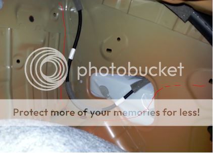


Maybe @ADExternal can help. ?Posted more information and really need some help with part 2 and any help big or small is appreciated.