Pauly99to17
Well-Known Member
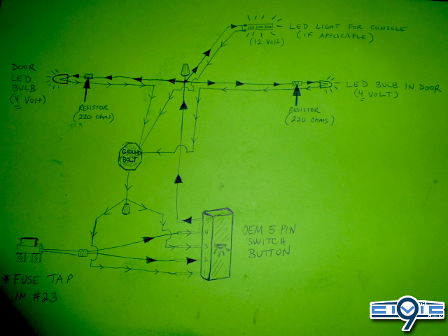
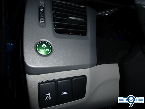
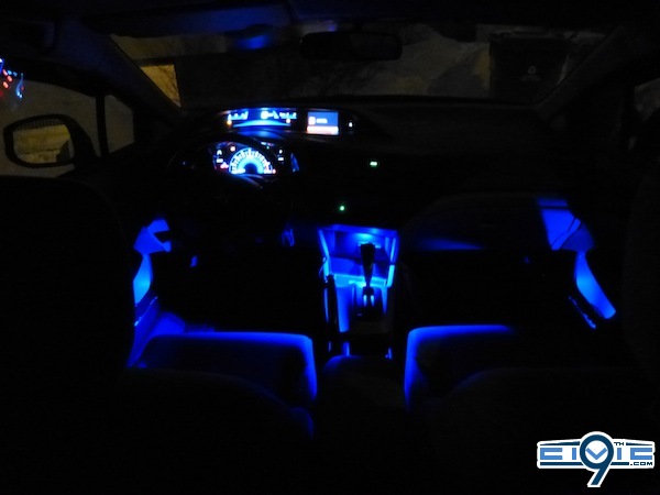
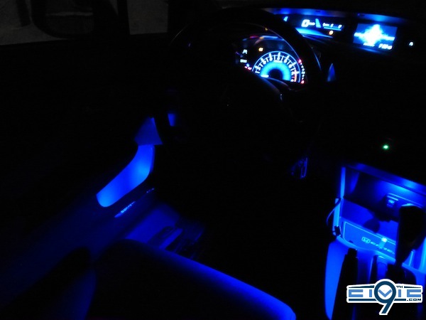
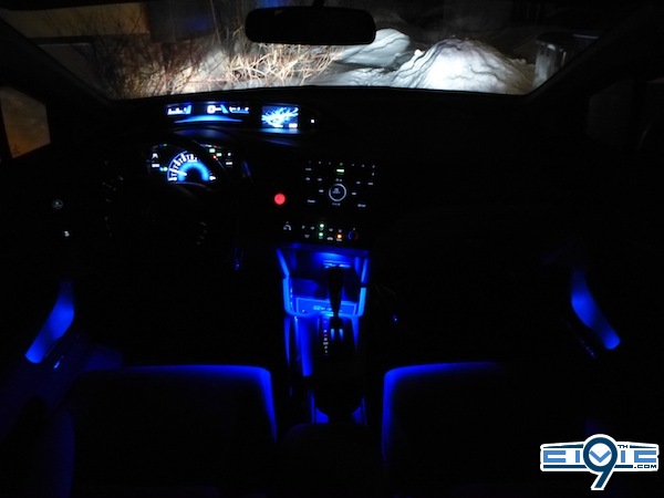
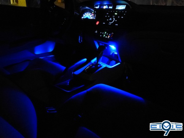
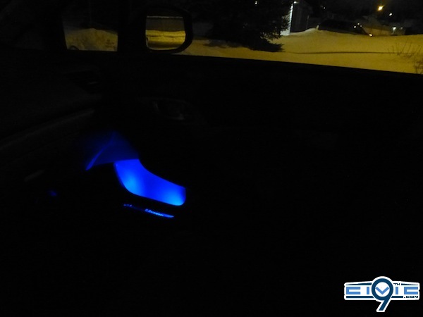
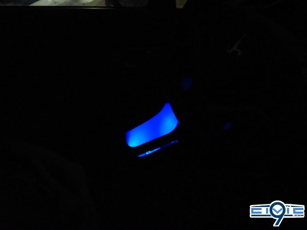
I added an LED bulb to each door compartment and they are wired to a light switch button. I also added my dash/console lighting to this circuit so it can be controlled by the switch too. Before now this dash/console light was wired to the 12 Volt plug behind shifter and always turned on....see my other DIY here: http://9thcivic.com/forum/threads/console-led-lighting.6603/
I certainly am no expert. I just had the idea and then figured everything out. Had some help from AlienPrime for the switch (You will see a link to his OEM 5 pin switch DIY below)This DIY is not all that difficult providing you have three things
1) The proper tools (Ex. a soldering iron,a Dremmel drill)
2) The OEM 5 pin switch plug (*More info. about this below)
3) Patience. Don't expect to have results within minutes.
The cost is about $40. Figure about 4 or 5 hours altogether, depending on how quickly you work.
***Following this DIY is at your own risk, neither I, nor this site, its owner or staff are responsible for any damage to your car or injuries.
Needed Materials
*Many of these materials are available at your local electronics shop (Ex.LED bulbs, marettes, resistors, wire). If you are patient enough to wait for shipping, you can order the materials from eBay and save a few bucks, but hardly seems worth it IMO. Plus, if you have any questions the electro-pros can help you out while you're getting everything.
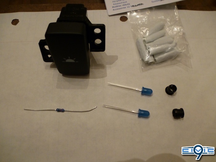
2 LED lights - 5 mm (or bigger if you want brighter light) - Get the type that diffuses the light, not the type that focuses light. You might want to pick up a 3rd one to add to the center panel. (?) Careful: LED bulbs with a blue condom over the bulb have a slightly different shade of blue than the blue LED bulbs that have a clear look. I suggest you get both to see which you prefer. *Important Update: See post #17 in this thread for an excellent bulb option!
(Bulb with resistor and wire already attached! No soldering needed if you go with this option!)
1 package of Ring Terminals for connecting to the ground bolt. (Only need 1 or 2 of these rings depending how you ground). Get the 1/4 " ones.
2 clip on bulb holders - 5 mm (Mine are black)
2 Resistors - 220 ohms - these will bring the voltage down from 12 Volts to 4 Volts (See "Important Update" above)
25 feet of wire is enough for doors. I got a little more because I had the console light to wire up too. I used 20 gauge wire.
1 OEM light switch button
(http://www.collegehillshondaparts.c..._in=all&search_str=08E10-TA0-1M035&make=honda)
*1 green plug for OEM switch Unavailable to buy separately (must buy ambient light kit $120 etc.) so check the auto wreckers. Not difficult to find.
***If you cannot find the plug then you will need to solder the wires to the 5 pins on the switch. See @AlienPrime's DIY: http://9thcivic.com/forum/threads/diy-honda-5-pin-magic-switch.6478/
1 Fuse Tap (http://www.ebay.com/itm/1-ADD-A-CIR..._Video_Fuses_Fuse_Holders&hash=item337f274430)
1 package of marettes to attach wiring
Some "filler metal" aka solder metal (*See "Important Update" above)
Some Electrical Tape
Some Duct tape
Some black Zip ties
*Only 1 resistor showing in pic....need two.
*Although not necessary I highly recommend you buy a 9 Volt battery that you can use to test the bulbs during the different stages of installation to make sure no connections have come loose from moving wires etc.)
***Attention: When testing with this battery you will need to attach a resistor to the circuit or you will overload and pop your LEDs which only take 4 Volts.
Tools I Used
*Soldering iron - See "Important Update" above (I bought one and am learning how....it's not that difficult. Lots of YouTube "How To" videos available) A good one on my other DIY (see link above)
Wire cutter/stripper tool
Dremmel Drill (a basic one will do the job) *Note a drill will not work because it is too big and you won't be able to get it into the tight space.
Flat head screw driver
Philips screw driver (+)
Good flash light comes in handy
Scissors
Utility blade
Pliers
Socket set to take off ground bolt.
Steps
To begin you will need to measure out and cut your wire. Make sure you leave more for the passengers side door becuase it is farther to connect to the power (fuse box).
*If you bought pre-attached resistor and wire and bulb you can skip over this step. (See "Important Update" above)
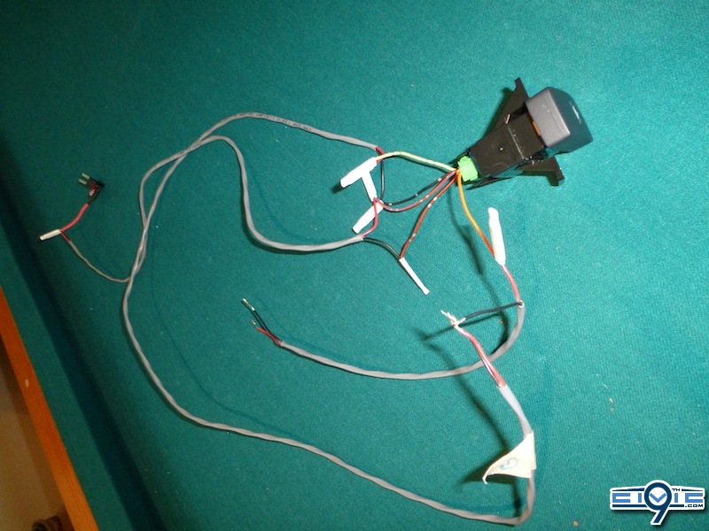
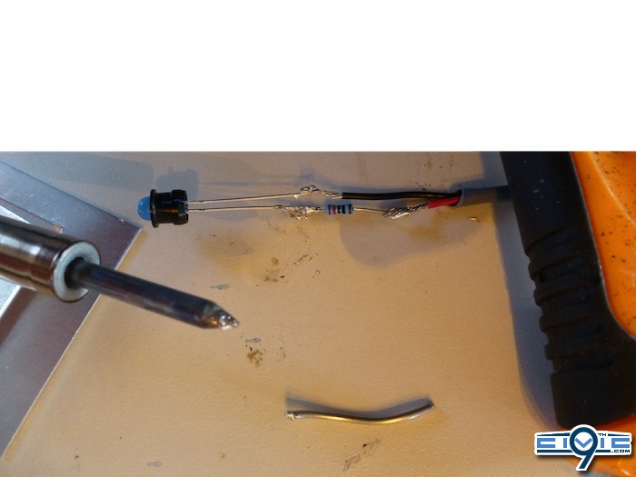
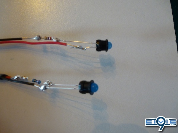
Next, solder your resistor and LED bulb to each set of wires. As you can see I am not good at this, but I got the job done and the connections are VERY solid...ha ha In this photo you can see the small black bulb holders as well as the resistors. I was often using my battery to test my connections.
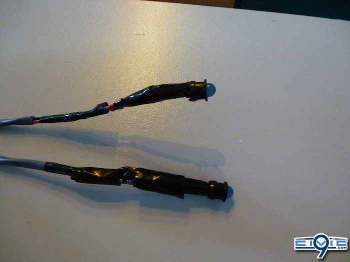
So, after soldering both I carefully and, as tightly as possible, wrapped each individual connection *seperately* so the positive and negative connections cannot touch which would cause a "short". THEN I wrapped the two wires together so that everything is tight and will fit throught the hole. (Photo below shows completed step) ***NOTE: Nothing can be wider than the outside ring of the black plastic bulb holder.
Now outside to the car. For those of you with garages...do you realize how lucky you are??!! ha ha
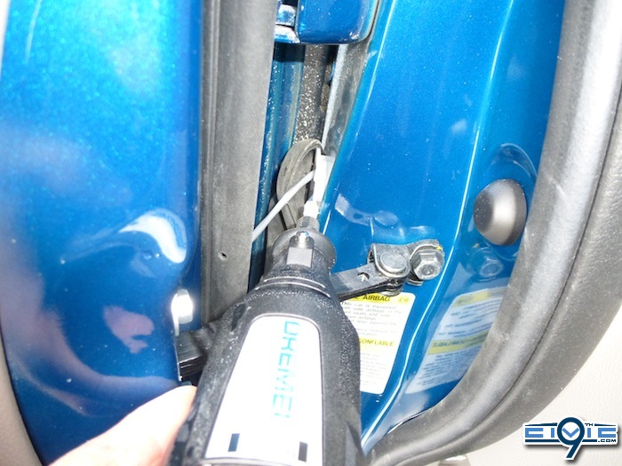
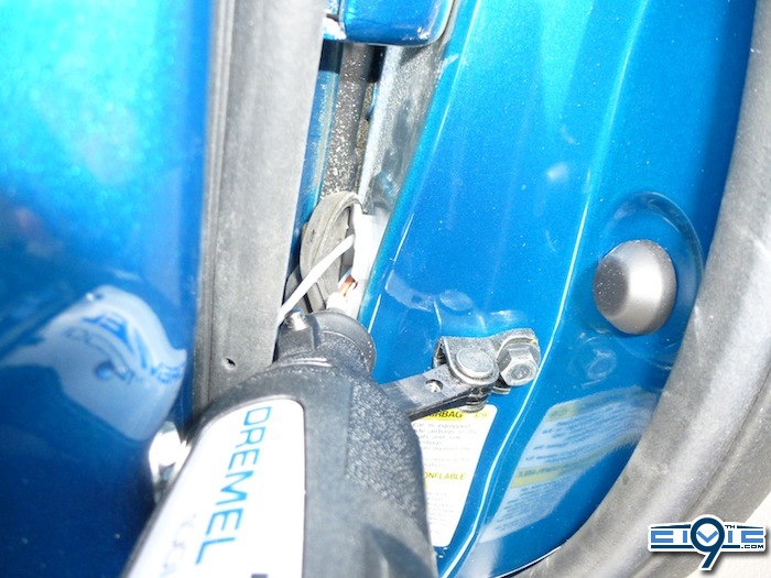
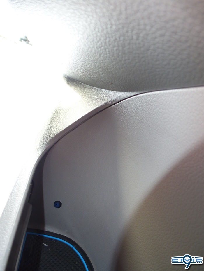
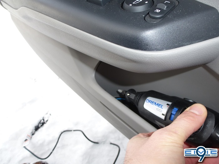
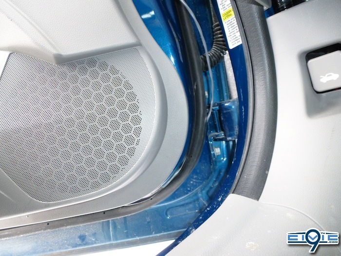
Dremmel drill time. ( IMPORTANT UPDATE: I moved my single LED from the hole in the door and changed it for a small LED light strip to have brighter lights here. I bought a small rectangular LED strip with 3 lights in it. I used 3M tape and attached it on the inside small plastic strip of the door just above the long slit you see in front of the compartment.) Use a pencil and make a little mark where you are going to put the hole. I would suggest that you put the hole close to the corner (see photo). *NOTE: Be VERY careful when drilling. Use a steady hand and be especially careful when the hole is finished that you don't accidentally touch the door plastic when turning the drill off or taking it out. This would leave an unwanted scratch that you would be very upset about. Also be VERY careful not to drill a hole that is too large or your light will end up sliding into the inside door space. You can always make the hole a little bigger, but you can't make it smaller so be patient with this step.
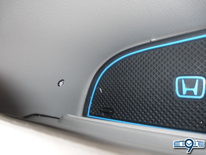
Thread the wire through hole and lift bottom of door panel wit your fingers so the wire can slide out the bottom. Gently pull all the wire through. Carefully place the light so it sits nicely in hole. If it does not fit well take the wire out and make hole slightly bigger and rethread wire.
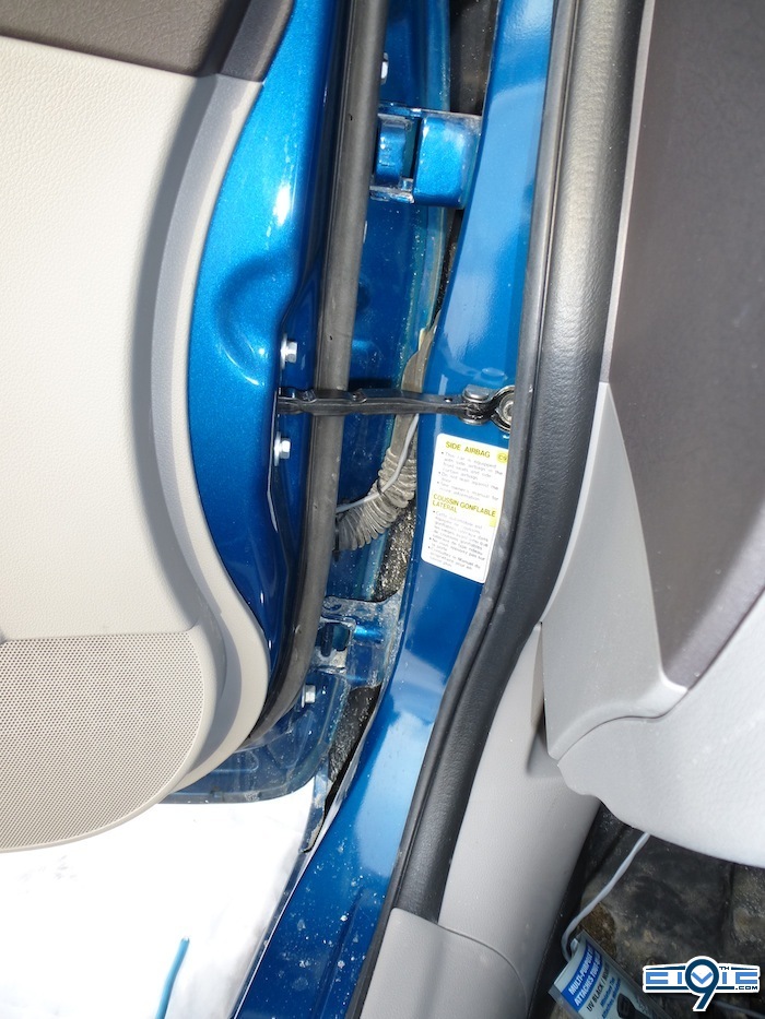
Now you just tuck wire under plastic panel up to the door hinge opening. You may want to add small pieces of duct tape to keep wire from slipping back out from under panel.

Next, lift rubber door seal and feed under.
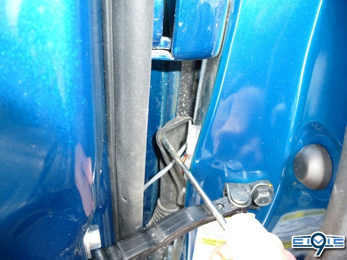
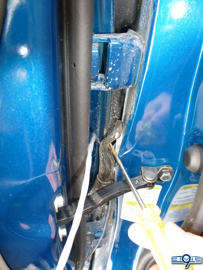
Put wire behind moving hinge (wire is actually in front in this photo) and lift rubber seal with screw driver. The little white plastic has a rounded hook thing pointing downwards. I used a screw driver and needle nose pliers to do this "operation". I only undid 1 of these little hook things: the top one you can see above my screwdriver.
I certainly am no expert. I just had the idea and then figured everything out. Had some help from AlienPrime for the switch (You will see a link to his OEM 5 pin switch DIY below)This DIY is not all that difficult providing you have three things
1) The proper tools (Ex. a soldering iron,a Dremmel drill)
2) The OEM 5 pin switch plug (*More info. about this below)
3) Patience. Don't expect to have results within minutes.
The cost is about $40. Figure about 4 or 5 hours altogether, depending on how quickly you work.
***Following this DIY is at your own risk, neither I, nor this site, its owner or staff are responsible for any damage to your car or injuries.
Needed Materials
*Many of these materials are available at your local electronics shop (Ex.LED bulbs, marettes, resistors, wire). If you are patient enough to wait for shipping, you can order the materials from eBay and save a few bucks, but hardly seems worth it IMO. Plus, if you have any questions the electro-pros can help you out while you're getting everything.
2 LED lights - 5 mm (or bigger if you want brighter light) - Get the type that diffuses the light, not the type that focuses light. You might want to pick up a 3rd one to add to the center panel. (?) Careful: LED bulbs with a blue condom over the bulb have a slightly different shade of blue than the blue LED bulbs that have a clear look. I suggest you get both to see which you prefer. *Important Update: See post #17 in this thread for an excellent bulb option!
(Bulb with resistor and wire already attached! No soldering needed if you go with this option!)
1 package of Ring Terminals for connecting to the ground bolt. (Only need 1 or 2 of these rings depending how you ground). Get the 1/4 " ones.
2 clip on bulb holders - 5 mm (Mine are black)
2 Resistors - 220 ohms - these will bring the voltage down from 12 Volts to 4 Volts (See "Important Update" above)
25 feet of wire is enough for doors. I got a little more because I had the console light to wire up too. I used 20 gauge wire.
1 OEM light switch button
(http://www.collegehillshondaparts.c..._in=all&search_str=08E10-TA0-1M035&make=honda)
*1 green plug for OEM switch Unavailable to buy separately (must buy ambient light kit $120 etc.) so check the auto wreckers. Not difficult to find.
***If you cannot find the plug then you will need to solder the wires to the 5 pins on the switch. See @AlienPrime's DIY: http://9thcivic.com/forum/threads/diy-honda-5-pin-magic-switch.6478/
1 Fuse Tap (http://www.ebay.com/itm/1-ADD-A-CIR..._Video_Fuses_Fuse_Holders&hash=item337f274430)
1 package of marettes to attach wiring
Some "filler metal" aka solder metal (*See "Important Update" above)
Some Electrical Tape
Some Duct tape
Some black Zip ties
*Only 1 resistor showing in pic....need two.
*Although not necessary I highly recommend you buy a 9 Volt battery that you can use to test the bulbs during the different stages of installation to make sure no connections have come loose from moving wires etc.)
***Attention: When testing with this battery you will need to attach a resistor to the circuit or you will overload and pop your LEDs which only take 4 Volts.
Tools I Used
*Soldering iron - See "Important Update" above (I bought one and am learning how....it's not that difficult. Lots of YouTube "How To" videos available) A good one on my other DIY (see link above)
Wire cutter/stripper tool
Dremmel Drill (a basic one will do the job) *Note a drill will not work because it is too big and you won't be able to get it into the tight space.
Flat head screw driver
Philips screw driver (+)
Good flash light comes in handy
Scissors
Utility blade
Pliers
Socket set to take off ground bolt.
Steps
To begin you will need to measure out and cut your wire. Make sure you leave more for the passengers side door becuase it is farther to connect to the power (fuse box).
*If you bought pre-attached resistor and wire and bulb you can skip over this step. (See "Important Update" above)
Next, solder your resistor and LED bulb to each set of wires. As you can see I am not good at this, but I got the job done and the connections are VERY solid...ha ha In this photo you can see the small black bulb holders as well as the resistors. I was often using my battery to test my connections.
So, after soldering both I carefully and, as tightly as possible, wrapped each individual connection *seperately* so the positive and negative connections cannot touch which would cause a "short". THEN I wrapped the two wires together so that everything is tight and will fit throught the hole. (Photo below shows completed step) ***NOTE: Nothing can be wider than the outside ring of the black plastic bulb holder.
Now outside to the car. For those of you with garages...do you realize how lucky you are??!! ha ha
Dremmel drill time. ( IMPORTANT UPDATE: I moved my single LED from the hole in the door and changed it for a small LED light strip to have brighter lights here. I bought a small rectangular LED strip with 3 lights in it. I used 3M tape and attached it on the inside small plastic strip of the door just above the long slit you see in front of the compartment.) Use a pencil and make a little mark where you are going to put the hole. I would suggest that you put the hole close to the corner (see photo). *NOTE: Be VERY careful when drilling. Use a steady hand and be especially careful when the hole is finished that you don't accidentally touch the door plastic when turning the drill off or taking it out. This would leave an unwanted scratch that you would be very upset about. Also be VERY careful not to drill a hole that is too large or your light will end up sliding into the inside door space. You can always make the hole a little bigger, but you can't make it smaller so be patient with this step.
Thread the wire through hole and lift bottom of door panel wit your fingers so the wire can slide out the bottom. Gently pull all the wire through. Carefully place the light so it sits nicely in hole. If it does not fit well take the wire out and make hole slightly bigger and rethread wire.
Now you just tuck wire under plastic panel up to the door hinge opening. You may want to add small pieces of duct tape to keep wire from slipping back out from under panel.
Next, lift rubber door seal and feed under.
Put wire behind moving hinge (wire is actually in front in this photo) and lift rubber seal with screw driver. The little white plastic has a rounded hook thing pointing downwards. I used a screw driver and needle nose pliers to do this "operation". I only undid 1 of these little hook things: the top one you can see above my screwdriver.
Last edited: