
Amomicivic
Well-Known Member
Installation of door courtesy lights on a LX sedan
DISCLAIMER:
· This mod calls for a lot of disassembly of the interior panels and cut all door panels, but all I can say is that they look terrific and very OEM.
· These instructions are for a 4 door civic sedan.
· I used VW parts because I could not find a Honda part that came as an assembly (lens, contacts and bulb holder) where I live, that was small enough to fit the spare space at the door panels and with the appropriate quality that gives an OEM look. Coupe owners should consider that maybe these lights could be a little small for the side of their door panels.
· A lot of work involved, but is not as complicated as it sounds.
· Remember that you do this mod at your own risk. I am not responsible for any damage done to your car or yourself as a result of doing this job.
Bill of materials:
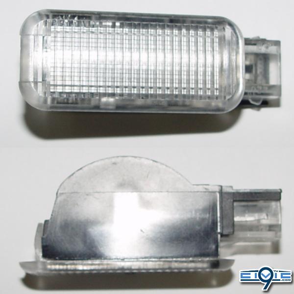
1. Four OEM VW courtesy lights – Part number 3B0-947-415.
2. 1 – OEM Honda light switch 08E10-TA0-1M035.
3. 1- Bussmann BP/HHH ATM Add-A-Fuse.
4. 1 – mini blade 3 amp fuse and 1 10 amp fuse.
5. 8 - T10 SMD 4 White LED Wedge (they already have resistors, so there is no necessity to buy more).
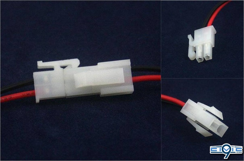
6. 5 – 2 pin power jack and plug wire and socket connector lead. Be sure that the wire is the same type and gauge that the cable you are buying (small note here: instead of one of these connectors, I first used a 4 pin connector with wires in order to lit the switch when the lights turned on, but when tried to borrow power from the closest switch available, the light did not work properly, so the plan was aborted).
7. 18 meters 16 AWG red cable for automotive use (22 or 24 AWG is OK, since power consumption is 1Amp @12V).
8. 16 meters 16 AWG black cable for automotive use (the same as above).
9. 9 - 22-18 Gauge Insulated Crimp-On Butt Connector.
10. 7- 22-18 Gauge Wire Tap-In Squeeze Connectors.
11. 1 - JVCC FELT-06 Polyester Felt Tape (1mm thick felt): ¾ in. x 75 ft. (Black). Great (mean it) for quelling those horrible noises.
12. 1 – Green masking tape.
13. Crimping tool
14. Soldering iron
15. 3M Super 33+ Vinyl electrical tape.
16. Hot melt gun and sticks.
17. Plastic wire ties.
18. Contact cement.
19. Strips of foam.
20. Sharp knife or an Exacto.
21. File.
22. Bubble level.
23. 2 wooden BBQ sticks
Estimate cost: $200
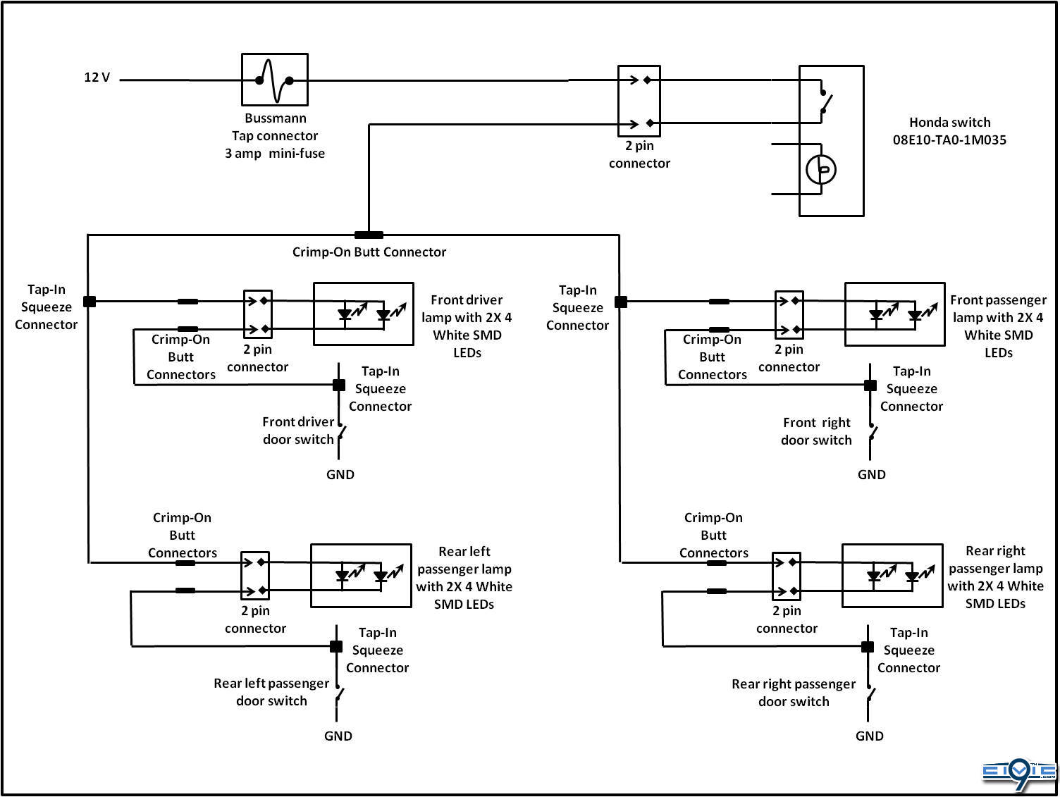
Circuit schematics
Instructions
1. Note: I did all described in this point because there were no bulbs with more LEDs available. If you can find a bulb with more LEDs that fits or just 4 LEDs is right for you, jump to the next step. Disassemble the lamp and remove the bulb. (Note here: you can use the bulb supplied, but then you will need a 12 amp circuit to power the lamps (produce more heat and more chances that has to be replaced) instead of the 1 amp with the LEDs). Then disassemble two SMD LED bulbs and solder them to the lamp, taking care to first check the polarity of the LED (normally, the resistor lead indicates the positive) and to solder the positive lead to the positive frame of the lamp.
3. Test the lamp and if works fine, put 2 small dots of hot melt glue on each side of the lamp.
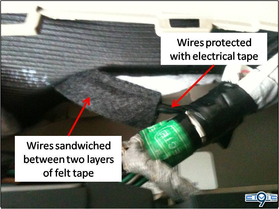
4. Glue foam around the socket using contact cement. Cover tightly the wires with electrical tape starting from the glue dots at the lamp. Finally, cover the tape with a sandwich of felt tape, for noise supression.
5. Push down in the middle of the lower portion of the back seat to gain access to the 10mm bolt that secures it to the car. Once removed, there are two plastic clips at each corner of the seat. At each corner, grab the clip, push the seat down and then pull the clip to release the seat. Now remove the lower portion of the rear seat.
6. Using a trim tool, start removing both rear floor garnishes by pulling up gently the side of the garnish that touches the rubber seal.
7. Then remove both front floor garnishes, by pulling first the lower part of the garnish and then pulling up the garnish that touches the rubber seal. Special mention to the driver side garnish: before removing it, you have to pull to the side the key cover and remove the screw.
8. Remove the rubber seals on both sides of the B pillar garnish. Remove the garnishes by pulling from the bottom until it pops out and then grabbing and pulling apart both sides of the garnish top before pulling.
9. Pull away the door seal and remove both kick panels.
10. Remove the glove box and the driver´s dashboard lower cover, to get access to the front door boots.
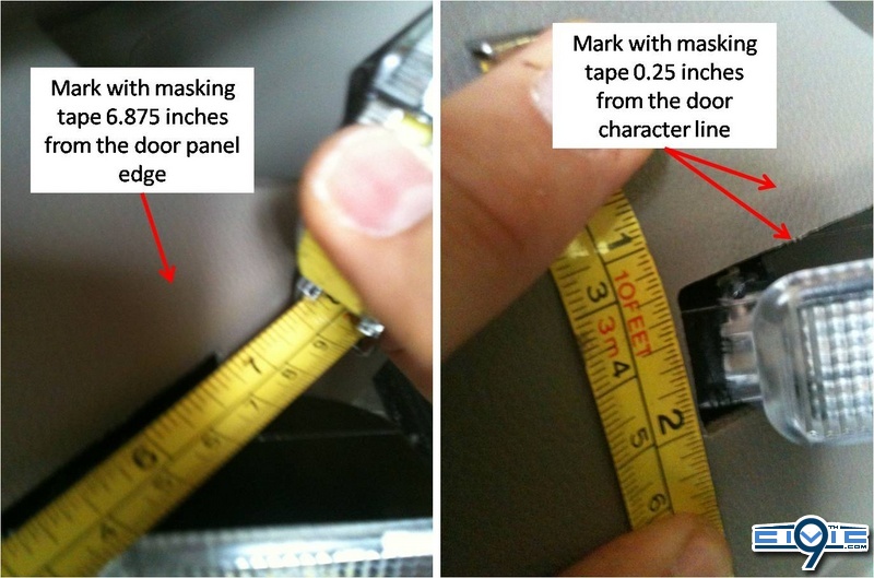
11. With the rear door in place and in a leveled floor, mark the door 6,875 inches horizontally from the edge of the panel and 0.25 inches down the character line. Cut a strip of masking tape of 4 inches and stick it horizontally to the door from the reference mark. Check the horizontally with the bubble level and adjust as necessary. Next, cut a two inches strip of masking tape and stick it in square angle to the first trip of masking tape. Check with the bubble level. Now, make a rectangle with masking tape that measures 1.875x0.7 inches, which the up-right corner is placed in the reference point. Cover the area around the rectangle with masking tape to avoid scratches.
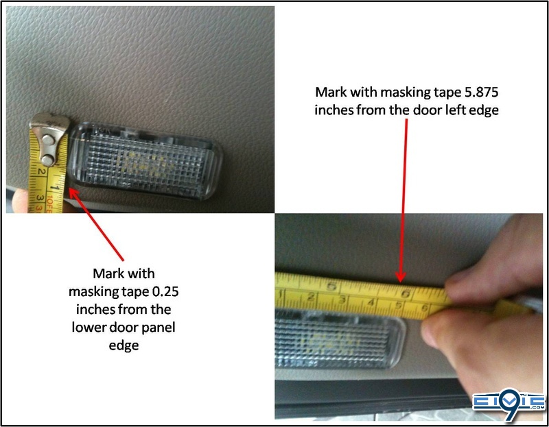
12. With the front door in place and in a leveled floor, mark the door 5.785 inches horizontally from the edge of the panel and 0.25 inches up from the door edge. Cut a strip of masking tape of 4 inches and stick it horizontally to the door from the reference mark. Check the horizontally with the bubble level and adjust as necessary. Next, cut a two inches strip of masking tape and stick it in square angle to the first trip of masking tape. Check with the bubble level. Now, make a rectangle with masking tape that measures 1.875x0.7 inches, which the lower-right corner is placed in the reference point. Cover the area around the rectangle with masking tape to avoid scratches.
13. Lower all windows and proceed to remove all four door panels (it is easier to remove the panels this way). Using a trim tool, remove the plastic cover behind door handle and remove the screw. Then look for a slot at the front of the switch panel and introduce the tool to pry it off, disconnect all wiring and unscrew the door panel. Then start removing the rear door panel from the lower right corner of the panel with the trim tool until it pops out. Finally, release the door handle and wires attached to it by pushing the top 2 clips on the inside. Reinstall the door handle on the door and screw it in position.
14. On the rear doors, to gain access to the wiring, lift the plastic protector from the lower front corner and secure it open with two pieces of masking tape. In case of the front doors, just remove the speakers to get access to the wiring. Unbolt the 8mm bolt and pull up the speaker and disconnect it.
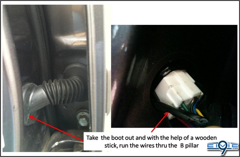
15. Starting with the rear left door, tie up together about 63 inches of a red and a black wire leaving an inch free at the beginning. Take out the door boot on both sides. Tape the wires to a BBQ wooden stick and using it as a guide, run the wires thru the door boot. Release the wires from the wooden stick and pull the wires about 12 inches with care of not damaging them.
16. With the help of the wooden stick, run the wires thru the boot to inside the door. Pull the wires about 44 inches. Use plastic ties to secure the wires to the existing car wiring. Take the wires out of the plastic cover in the same place where the window connectors poke out. Using two crimp-on butt connectors, connect the plug connector (male) to the wiring just placed (red with red and black with black). Cover the butt connectors with electrical tape and finally, sandwich the wires with felt tape.
17. Look for the rear left door switch and using a tap connector, connect the black wire that comes from the door to the wire that goes to the switch and cut the excess. Use electrical tape and plastic ties to tidy the wiring.
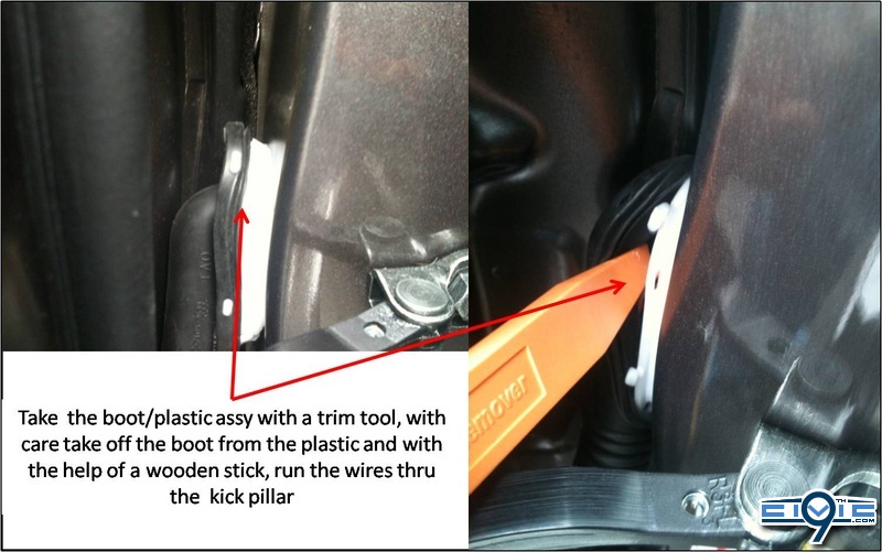
18. Continuing with the front left door, tie up together about 63 inches of a red and a black wire leaving an inch free at the beginning. With care, take off the boot/plastic assy from the car with a trim too and next take off the boot from the plastic. Tape the wires to a BBQ wooden stick and using it as a guide, run the wires thru the door boot. Release the wires from the wooden stick and pull the wires about 12 inches with care of not damaging them
19. Again, with the help of the wooden stick, run the wires thru the boot to inside the door. Pull the wires about 54 inches. Use plastic ties to secure the wires to the existing car wiring. Take the wires out of the plastic cover in the same place where the window connectors poke out. Using two crimp-on butt connectors, connect the plug connector (male) to the wiring just placed (red with red and black with black). Cover the butt connectors with electrical tape and finally, sandwich the wires with felt tape.
20. Look for the front left door switch at the B pillar and using a tap connector, connect the black wire that comes from the door to the wire that goes to the switch. Run the red wire that comes from the rear door next to the black wire that comes from the front door. Run the red wire close to the existing car wiring and close to the fuse box. Leave about 40inches spare and cut the wire. Use electrical tape and plastic ties to tidy the wiring.
21. Repeat the same for the other side with two differences. The first, there is no OEM wires at the passenger sill. What I did, I slicked two double layers of felt tape all the way where the wires were going to be run and then secure them in place with 2 inch each pieces of felt tape. The other difference is that you have to run the red wire behind the dash to meet the other red cable close to the fuse box. In order to avoid noises, use plastic ties and felt tape as needed.
22. Cut the door panels using a sharp knife. The secret for a snug fit is to stop cutting before the lamp can be placed and start using the file to keep opening the hole. Remember, you can always make the hole bigger, not smaller.
23. Once a lamp is installed al each door, reinstall the door panels starting from the top and connecting the socket/plug before pushing the panels in position. Remember to push the door panels around the door handle also. Screw the door panel in place.
24. Grab the last 2 pin connector plug and connect the red wire to the Bussmann fuse tap using the crimping tool. And the black wire of the plug to the red wires using a butt connector. Protect the connections with electrical tape and tidy the wiring with plastic ties.
26. Solder the 2 pin socket to pins 4 and 5 of the Honda switch. Use hot melt glue to fill the space and tape the wires together with electrical tape. Install the switch in the driver´s dash lower cover in place of one cover
27. Reinstall the glove box, connect the wires and reinstall the driver´s dash lower cover.
28. DONE!!
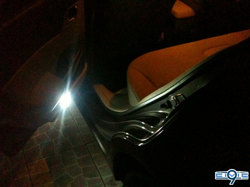
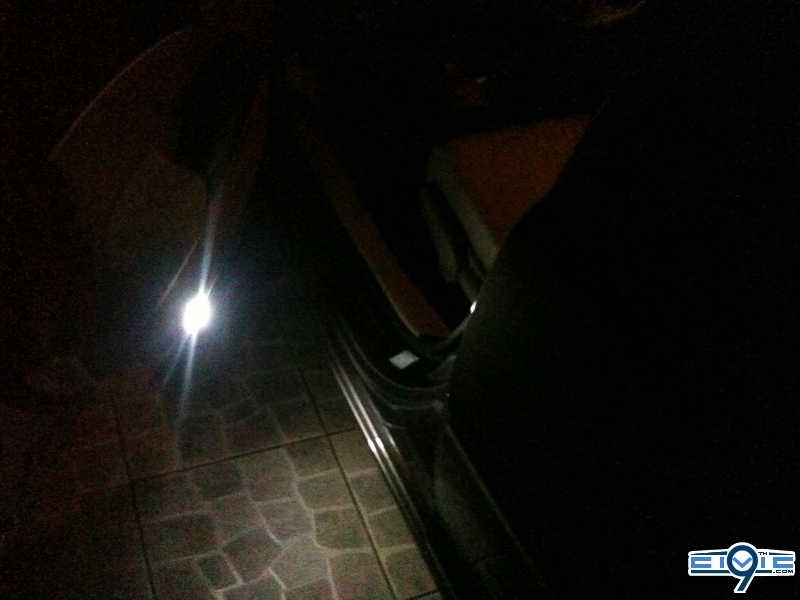
night shots:
Questions? Glad to anwser.
DISCLAIMER:
· This mod calls for a lot of disassembly of the interior panels and cut all door panels, but all I can say is that they look terrific and very OEM.
· These instructions are for a 4 door civic sedan.
· I used VW parts because I could not find a Honda part that came as an assembly (lens, contacts and bulb holder) where I live, that was small enough to fit the spare space at the door panels and with the appropriate quality that gives an OEM look. Coupe owners should consider that maybe these lights could be a little small for the side of their door panels.
· A lot of work involved, but is not as complicated as it sounds.
· Remember that you do this mod at your own risk. I am not responsible for any damage done to your car or yourself as a result of doing this job.
Bill of materials:
1. Four OEM VW courtesy lights – Part number 3B0-947-415.
2. 1 – OEM Honda light switch 08E10-TA0-1M035.
3. 1- Bussmann BP/HHH ATM Add-A-Fuse.
4. 1 – mini blade 3 amp fuse and 1 10 amp fuse.
5. 8 - T10 SMD 4 White LED Wedge (they already have resistors, so there is no necessity to buy more).
6. 5 – 2 pin power jack and plug wire and socket connector lead. Be sure that the wire is the same type and gauge that the cable you are buying (small note here: instead of one of these connectors, I first used a 4 pin connector with wires in order to lit the switch when the lights turned on, but when tried to borrow power from the closest switch available, the light did not work properly, so the plan was aborted).
7. 18 meters 16 AWG red cable for automotive use (22 or 24 AWG is OK, since power consumption is 1Amp @12V).
8. 16 meters 16 AWG black cable for automotive use (the same as above).
9. 9 - 22-18 Gauge Insulated Crimp-On Butt Connector.
10. 7- 22-18 Gauge Wire Tap-In Squeeze Connectors.
11. 1 - JVCC FELT-06 Polyester Felt Tape (1mm thick felt): ¾ in. x 75 ft. (Black). Great (mean it) for quelling those horrible noises.
12. 1 – Green masking tape.
13. Crimping tool
14. Soldering iron
15. 3M Super 33+ Vinyl electrical tape.
16. Hot melt gun and sticks.
17. Plastic wire ties.
18. Contact cement.
19. Strips of foam.
20. Sharp knife or an Exacto.
21. File.
22. Bubble level.
23. 2 wooden BBQ sticks
Estimate cost: $200
Circuit schematics
Instructions
1. Note: I did all described in this point because there were no bulbs with more LEDs available. If you can find a bulb with more LEDs that fits or just 4 LEDs is right for you, jump to the next step. Disassemble the lamp and remove the bulb. (Note here: you can use the bulb supplied, but then you will need a 12 amp circuit to power the lamps (produce more heat and more chances that has to be replaced) instead of the 1 amp with the LEDs). Then disassemble two SMD LED bulbs and solder them to the lamp, taking care to first check the polarity of the LED (normally, the resistor lead indicates the positive) and to solder the positive lead to the positive frame of the lamp.
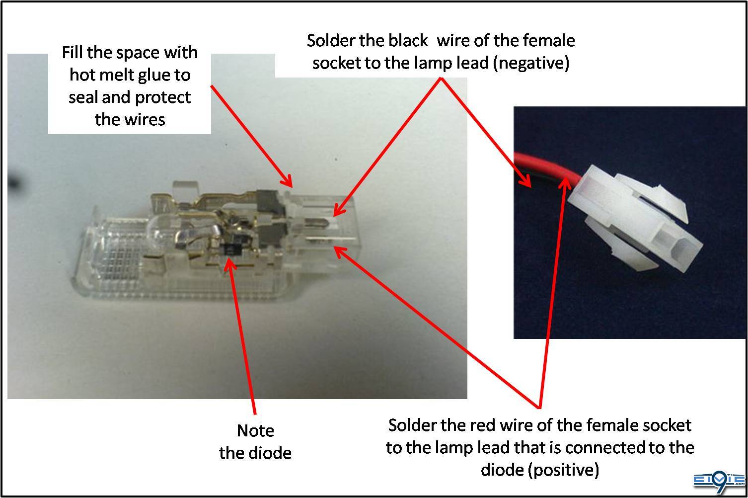
2. Disassemble one 2 pin power jack and plug wire and socket connector lead, separate the terminals and solder the red and black wires with the socket as shown in figure. The fill the space with hot melt glue.
3. Test the lamp and if works fine, put 2 small dots of hot melt glue on each side of the lamp.
4. Glue foam around the socket using contact cement. Cover tightly the wires with electrical tape starting from the glue dots at the lamp. Finally, cover the tape with a sandwich of felt tape, for noise supression.
5. Push down in the middle of the lower portion of the back seat to gain access to the 10mm bolt that secures it to the car. Once removed, there are two plastic clips at each corner of the seat. At each corner, grab the clip, push the seat down and then pull the clip to release the seat. Now remove the lower portion of the rear seat.
6. Using a trim tool, start removing both rear floor garnishes by pulling up gently the side of the garnish that touches the rubber seal.
7. Then remove both front floor garnishes, by pulling first the lower part of the garnish and then pulling up the garnish that touches the rubber seal. Special mention to the driver side garnish: before removing it, you have to pull to the side the key cover and remove the screw.
8. Remove the rubber seals on both sides of the B pillar garnish. Remove the garnishes by pulling from the bottom until it pops out and then grabbing and pulling apart both sides of the garnish top before pulling.
9. Pull away the door seal and remove both kick panels.
10. Remove the glove box and the driver´s dashboard lower cover, to get access to the front door boots.
11. With the rear door in place and in a leveled floor, mark the door 6,875 inches horizontally from the edge of the panel and 0.25 inches down the character line. Cut a strip of masking tape of 4 inches and stick it horizontally to the door from the reference mark. Check the horizontally with the bubble level and adjust as necessary. Next, cut a two inches strip of masking tape and stick it in square angle to the first trip of masking tape. Check with the bubble level. Now, make a rectangle with masking tape that measures 1.875x0.7 inches, which the up-right corner is placed in the reference point. Cover the area around the rectangle with masking tape to avoid scratches.
12. With the front door in place and in a leveled floor, mark the door 5.785 inches horizontally from the edge of the panel and 0.25 inches up from the door edge. Cut a strip of masking tape of 4 inches and stick it horizontally to the door from the reference mark. Check the horizontally with the bubble level and adjust as necessary. Next, cut a two inches strip of masking tape and stick it in square angle to the first trip of masking tape. Check with the bubble level. Now, make a rectangle with masking tape that measures 1.875x0.7 inches, which the lower-right corner is placed in the reference point. Cover the area around the rectangle with masking tape to avoid scratches.
13. Lower all windows and proceed to remove all four door panels (it is easier to remove the panels this way). Using a trim tool, remove the plastic cover behind door handle and remove the screw. Then look for a slot at the front of the switch panel and introduce the tool to pry it off, disconnect all wiring and unscrew the door panel. Then start removing the rear door panel from the lower right corner of the panel with the trim tool until it pops out. Finally, release the door handle and wires attached to it by pushing the top 2 clips on the inside. Reinstall the door handle on the door and screw it in position.
14. On the rear doors, to gain access to the wiring, lift the plastic protector from the lower front corner and secure it open with two pieces of masking tape. In case of the front doors, just remove the speakers to get access to the wiring. Unbolt the 8mm bolt and pull up the speaker and disconnect it.
15. Starting with the rear left door, tie up together about 63 inches of a red and a black wire leaving an inch free at the beginning. Take out the door boot on both sides. Tape the wires to a BBQ wooden stick and using it as a guide, run the wires thru the door boot. Release the wires from the wooden stick and pull the wires about 12 inches with care of not damaging them.
16. With the help of the wooden stick, run the wires thru the boot to inside the door. Pull the wires about 44 inches. Use plastic ties to secure the wires to the existing car wiring. Take the wires out of the plastic cover in the same place where the window connectors poke out. Using two crimp-on butt connectors, connect the plug connector (male) to the wiring just placed (red with red and black with black). Cover the butt connectors with electrical tape and finally, sandwich the wires with felt tape.
17. Look for the rear left door switch and using a tap connector, connect the black wire that comes from the door to the wire that goes to the switch and cut the excess. Use electrical tape and plastic ties to tidy the wiring.
18. Continuing with the front left door, tie up together about 63 inches of a red and a black wire leaving an inch free at the beginning. With care, take off the boot/plastic assy from the car with a trim too and next take off the boot from the plastic. Tape the wires to a BBQ wooden stick and using it as a guide, run the wires thru the door boot. Release the wires from the wooden stick and pull the wires about 12 inches with care of not damaging them
19. Again, with the help of the wooden stick, run the wires thru the boot to inside the door. Pull the wires about 54 inches. Use plastic ties to secure the wires to the existing car wiring. Take the wires out of the plastic cover in the same place where the window connectors poke out. Using two crimp-on butt connectors, connect the plug connector (male) to the wiring just placed (red with red and black with black). Cover the butt connectors with electrical tape and finally, sandwich the wires with felt tape.
20. Look for the front left door switch at the B pillar and using a tap connector, connect the black wire that comes from the door to the wire that goes to the switch. Run the red wire that comes from the rear door next to the black wire that comes from the front door. Run the red wire close to the existing car wiring and close to the fuse box. Leave about 40inches spare and cut the wire. Use electrical tape and plastic ties to tidy the wiring.
21. Repeat the same for the other side with two differences. The first, there is no OEM wires at the passenger sill. What I did, I slicked two double layers of felt tape all the way where the wires were going to be run and then secure them in place with 2 inch each pieces of felt tape. The other difference is that you have to run the red wire behind the dash to meet the other red cable close to the fuse box. In order to avoid noises, use plastic ties and felt tape as needed.
22. Cut the door panels using a sharp knife. The secret for a snug fit is to stop cutting before the lamp can be placed and start using the file to keep opening the hole. Remember, you can always make the hole bigger, not smaller.
23. Once a lamp is installed al each door, reinstall the door panels starting from the top and connecting the socket/plug before pushing the panels in position. Remember to push the door panels around the door handle also. Screw the door panel in place.
24. Grab the last 2 pin connector plug and connect the red wire to the Bussmann fuse tap using the crimping tool. And the black wire of the plug to the red wires using a butt connector. Protect the connections with electrical tape and tidy the wiring with plastic ties.
25. I used the 26 position in the fuse box to connect the fuse tap. That´s the lighter circuit. Since I don´t smoke and rarely use it, I changed the 15 Amp fuse to a 10 Amp and used a 3 Amp fuse for the courtesy lights.
26. Solder the 2 pin socket to pins 4 and 5 of the Honda switch. Use hot melt glue to fill the space and tape the wires together with electrical tape. Install the switch in the driver´s dash lower cover in place of one cover
27. Reinstall the glove box, connect the wires and reinstall the driver´s dash lower cover.
28. DONE!!
night shots:
Questions? Glad to anwser.
Last edited by a moderator:


")