Navigation
Install the app
How to install the app on iOS
Follow along with the video below to see how to install our site as a web app on your home screen.
Note: This feature may not be available in some browsers.
More options
You are using an out of date browser. It may not display this or other websites correctly.
You should upgrade or use an alternative browser.
You should upgrade or use an alternative browser.
DIY DIY - Honda 5 Pin Magic Switch!
- Thread starter AlienPrime
- Start date
Dtaggart
Well-Known Member
by any chance can you tell me exactly were everything is suppose to get connected? I can't even get the switch to light up and I have everything attached like you had in your photo. does the positive "to light need to be connected to something for it to work? or just for testing sake can I just connect the "feed" wires to the battery and ground to the frame? I am just lost, the diagram posted really doesn't help total noobs what can go were or how to test this.
also another question for this image are all three center prongs soldered together?
http://i.imgur.com/k5eRN7Zl.jpg
but the it shows that he connect pins 1&3 2&4 with electrical tape.
I am just really confused
also another question for this image are all three center prongs soldered together?
http://i.imgur.com/k5eRN7Zl.jpg
but the it shows that he connect pins 1&3 2&4 with electrical tape.
I am just really confused
Dtaggart
i think the orginal post is helpful as long as you read it a few times.
i did not solder the 3 center pins together, it just looks like that because i cant solder well but they are all seperate.
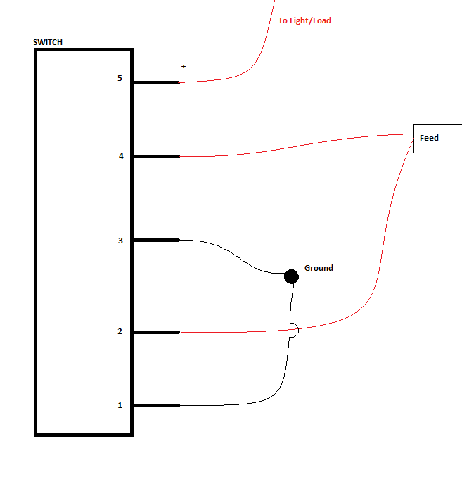
Like the diagram points out
Pins 1&3 both connect to a ground.
Pins 2&4 go to your power source (usually a fuse)
and pin 5 goes to whatever needs power (usually LEDs)
i think the orginal post is helpful as long as you read it a few times.
WITH THE LIGHT ICON POINTING DOWN LIKE SO:
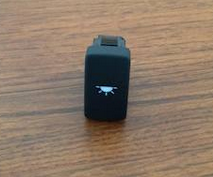
Pin 5- Positive, this completes the circuit for the on/off function
Pin 4- Power for switch
Pin 3- GROUND for Switch
Pin 2- Power/Live wire for illumination
Pin 1- GROUND for illumination
i did not solder the 3 center pins together, it just looks like that because i cant solder well but they are all seperate.
Like the diagram points out
Pins 1&3 both connect to a ground.
Pins 2&4 go to your power source (usually a fuse)
and pin 5 goes to whatever needs power (usually LEDs)
Last edited:
Dtaggart
Well-Known Member
ok for pin 5 does it need to be connected to something in order for the switch to work?
If I want to test just the switch can it be connected directly to the battery?
I have LEDGlow lights and if I under stand this correctly I will attach pin 5 to them.
Ledglows controllers have a ground wire too. but since I am grounding them in the switch do I still need to ground them from the LedGlow controller?
Thanks
i have the same LEDs and i hooked them to the switch.
you'll connect the LEDGlow ground to the switch ground wires, then all three will have to be bolted to the frame somewhere to serve as a ground.
pin 5 will go to the LEDs, but you cant connect straight to the battery.
do you have an add-a-circuit adapter like this?
http://i165.photobucket.com/albums/u55/t_pilot/add-a-circuit.jpg
you can pick it up at any autozone/napa/advance
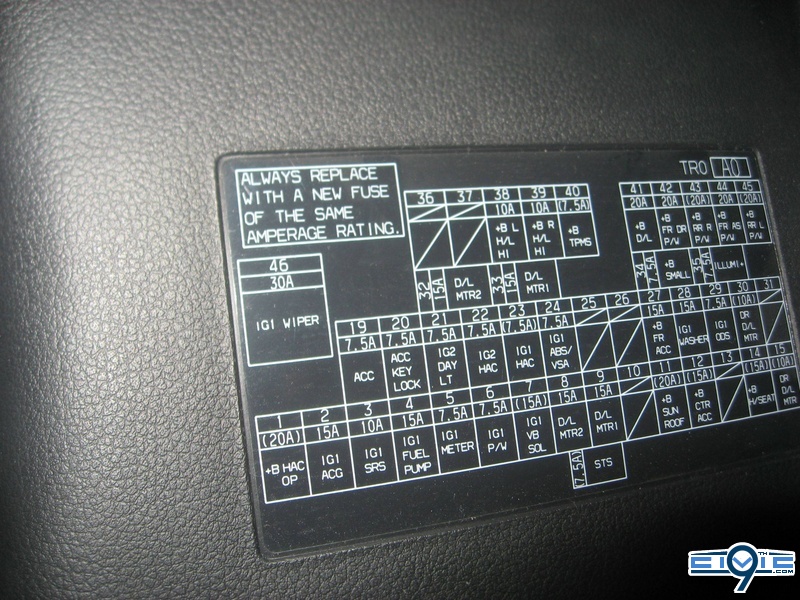
connect that to fuse #23 with a 10A fuse and you'll be good to go!
you'll connect the LEDGlow ground to the switch ground wires, then all three will have to be bolted to the frame somewhere to serve as a ground.
pin 5 will go to the LEDs, but you cant connect straight to the battery.
do you have an add-a-circuit adapter like this?
http://i165.photobucket.com/albums/u55/t_pilot/add-a-circuit.jpg
you can pick it up at any autozone/napa/advance
connect that to fuse #23 with a 10A fuse and you'll be good to go!
Dtaggart
Well-Known Member
I do I have two but not the right fuses to go in them even tho they fit in the fuse slot. I ordered low profile ones yesterday tho
I managed to get the light on by doing the same thing in the video with a old 12v adapter I had laying around.
I didn't want to start until I got it working and I could confirm the actual switch was working.
Also will fuse 23 go on and off with the car? I dont have any fuse in that slot but I can just grab one from my fuse box and plug it in
thanks again
Last edited:
Dtaggart
The adapter will go into the slot, then the fuse into the adapter.
And yes, slot 23 comes on with the ignition, and turns off with it too.
Slot 23 is used for Honda's ambient lighting kit, so it's perfect for this application
The adapter will go into the slot, then the fuse into the adapter.
And yes, slot 23 comes on with the ignition, and turns off with it too.
Slot 23 is used for Honda's ambient lighting kit, so it's perfect for this application
Pauly99to17
Well-Known Member
Maybe this diagram will help you out.....by any chance can you tell me exactly were everything is suppose to get connected? I can't even get the switch to light up and I have everything attached like you had in your photo. does the positive "to light need to be connected to something for it to work? or just for testing sake can I just connect the "feed" wires to the battery and ground to the frame? I am just lost, the diagram posted really doesn't help total noobs what can go were or how to test this.
also another question for this image are all three center prongs soldered together?
http://i.imgur.com/k5eRN7Zl.jpg
but the it shows that he connect pins 1&3 2&4 with electrical tape.
I am just really confused

- Thread starter
- #89
AlienPrime
Well-Known Member
uhhh... isnt fuse 23 ignition HAC? lol ambient lighting fuse is only 7.5A and it's #35Dtaggart
The adapter will go into the slot, then the fuse into the adapter.
And yes, slot 23 comes on with the ignition, and turns off with it too.
Slot 23 is used for Honda's ambient lighting kit, so it's perfect for this application
- Thread starter
- #90
AlienPrime
Well-Known Member
- Thread starter
- #91
AlienPrime
Well-Known Member
this is a helpful thread btw lol
http://9thcivic.com/forum/threads/electrical-work-inside-outside-your-car.6919/
http://9thcivic.com/forum/threads/electrical-work-inside-outside-your-car.6919/
Dtaggart
Well-Known Member
Well I hooked it all up and its banging. 23 turns on when you turn the key one click. AlienPrime is right 35 is Ambient, 23 work just as well though.
My next project is tying my lights in with my domes
Thanks for all the help really appreciate it.
My next project is tying my lights in with my domes
Thanks for all the help really appreciate it.
Pauly99to17
Well-Known Member
Check the illuminated door sill DIY to see which wires control dome lights.Well I hooked it all up and its banging. 23 turns on when you turn the key one click. AlienPrime is right 35 is Ambient, 23 work just as well though.
My next project is tying my lights in with my domes
Thanks for all the help really appreciate it.
Pauly99to17
Well-Known Member
Well, I just spent a few hours trouble shooting this dam switch and I will post this here in case anyone else ever has this problem. After fixing a rattle, I put my dash back together and plugged all my switches back in only to find out that my ambient lights were not working. I checked the fuse and it was blown. replaced it only to have it blow again. So i figure there has got to be a short. I check and double check all wires and could not figure it out for the life of me. Finally I brought the switch into the house and took it apart. Thanks to @323 for putting pictures and showing me that this could be done. I tested all the wiring in the switch and could get the light in the button to work, but could not get my LED that was controlled by the switch to work. I ended up narrowing it down to pin #5 which is where the power supply comes out of the switch. I took a small pin and just bent the small metal contacts (the actual switch contacts) upwards hoping that it would make a more solid connection and maybe solve the problem. It worked. Yahoo!
Last edited:
- Thread starter
- #96
AlienPrime
Well-Known Member
Yay finally fixed! Hahaha ")
- Thread starter
- #98
AlienPrime
Well-Known Member
if the 5th pin wasnt making connection this would not have caused a short. Pin 4 and 3 could have been connected somehow. Or your feed was looped to a grounded ground. Or you were feeding power into a ground without a resistive load :/Well, I just spent a few hours trouble shooting this dam switch and I will post this here in case anyone else ever has this problem. After fixing a rattle, I put my dash back together and plugged all my switches back in only to find out that my ambient lights were not working. I checked the fuse and it was blown. replaced it only to have it blow again. So i figure there has got to be a short. I check and double check all wires and could not figure it out for the life of me. Finally I brought the switch into the house and took it apart. Thanks to @323 for putting pictures and showing me that this could be done. I tested all the wiring in the switch and could get the light in the button to work, but could not get my LED that was controlled by the switch to work. I ended up narrowing it down to pin #5 which is where the power supply comes out of the switch. I took a small pin and just bent the small metal contacts (the actual switch contacts) upwards hoping that it would make a more solid connection and maybe solve the problem. It worked. Yahoo!
Pauly99to17
Well-Known Member
It was the little metal piece that has two prongs that moves into position when clicked on.if the 5th pin wasnt making connection this would not have caused a short. Pin 4 and 3 could have been connected somehow. Or your feed was looped to a grounded ground. Or you were feeding power into a ground without a resistive load :/
When it is clicked "ON" the 2 thin metal pieces connect the 2 tiny circuits. (Connecting pins 4 and 5) I just bent them up a little bit so there would be a more solid contact and it did the trick.
Pauly99to17
Well-Known Member
Ya, maybe the contact was so weak and inconsistent that it cause the short. ???if the 5th pin wasnt making connection this would not have caused a short. Pin 4 and 3 could have been connected somehow. Or your feed was looped to a grounded ground. Or you were feeding power into a ground without a resistive load :/