big 3 - basically the same situation, but this was done on the r18 engine (non-si) from the 8th gen civic, but it's basically identical. Pics towards the bottom show what is done.
===========
Since there seem to be a lot of questions & confusion about how to to properly upgrade "The Big Three", I'm going to make this post - Its really very simple once you understand what you are trying to accomplish:
1. - What you are trying to accomplish:
By doing the big three upgrade, you are creating a route for current to flow between the alternator & battery & back again, with minimal resistance. The way you do this is by using short runs of large gauge power cable (preferably 1/0 AWG, but 4AWG may work - depending on the load) to connect the items. It is known as "The Big Three" because you make 3 connections, which I list below in the order in which the circuit functions:
Connection #1: This is a piece of positive cable, run between the alternator output terminal (the nut on top of the alternator under the rubber boot) and the positive battery terminal. Ideally, you should fuse this wire near the battery, but many people forego this step.
Connection #2: This is a piece of negative cable, run from the negative battery terminal to a solid point on the engine block.
Connection #3: This is a piece of negative cable, run either between the chassis of the car and the engine block or between the chassis of the car & the negative battery terminal - (both accomplish the same thing).
2. What the items do and how the circuit works:
As mentioned earlier, the idea is to allow unencumbered flow of current between the alternator & battery, and back again. The way the circuit functions is as follows:
1. - Current is generated by the alternator, & output through its terminal lug.
2. - This current flows through the 1st (positive) big three cable into the positive battery terminal.
3. - The negative battery termimal needs to be grounded for the circuit to complete, and allow flow of power. Therefore, the "path of flow" continues through the battery, out of the negative battery terminal.
4. - The "path of flow" continues through the 2nd (ground) big three cable into the metal engine block.
5. - Since the metal engine block makes contact with the alternator case, grounding the unit, the circuit is completed.
NOTICE - WE DIDN'T MENTION THE LAST (3rd) BIG THREE CABLE.
The reason we didn't do so is because technically, it is not a necessary part of alternator/battery circuit. However, other electrical items in the vehicle have their grounds connected directly to the chassis of the vehicle. In order for these items to function, we need to tie the chassis of the car into the battery/alternator circuit.
This is where the 3rd and final "Big Three" cable comes in. We need to run another ground cable - either between the chassis & the engine block, or between the chassis & the battery negative terminal - in essence coupling the circuits.
3. - OK.... But how did the car work without having the "Big Three" cables in place before?
The answer to this is that there already are these connections in place, from the factory... they just are not very efficient and use small gauge wire. If you look at the alternator, you will see there is a wire coming out of it that goes to the fuse box, & battery. This is the main power wire. You will also see that there are wires from the battery to the chassis, & to the engine block. These wires create the necessary continuity to allow current flow throughout the car's electrical system... but they cannot support the added current draw things like high power audio devices put on the system. The resistance they create when trying to draw large ammounts of electrical current causes the voltage to drop, and this generates heat in both the cables themselves and your electronic devices, as well as dimming of your lights, etc.
4. - So how do you connect these new pieces of wire to the car?
There are various ways to connect the cables to the battery, some better than others. But for the connections to the alternator output lug, engine block, & vehicle chassis, crimp on ring terminals are by far the best. This terminates the cable into a flat plate with a hole in the middle, which can be screwed into place with a nut or bolt. To install the crimp ends properly, you obviously need terminals with the correct size crimp end for the wire you are using, as well as a way to strip said wire, and a crimp tool. I won't go into detail here about where to acquire a crimp tool, ring terminal ends, or how to install them. If you need help with that feel free to PM me.
5. - So when I upgrade, do I leave the factory wires in place or replace them completely?
You can leave the factory wires in place - they aren't hurting anything, especially on the positive side. The factory wiring that goes to the fuse box can & should remain on the alternator output terminal as well as the new positive "big three" cable. Don't worry about the factory wires causing resistance by being left in place. The way electricity works, it always takes the path of least resistance. Given the choice of a short, thick run of cable going to the same place as a long, thin one, it will choose the direct route and use the larger, shorter cable for the majority of the power transfer process.
5a. - Factory alternator output terminal clearance issues:
I will note at this point (albeit a tad early in the DIY) that in order to get the needed clearance to connect the new large gauge cable ring terminal to the alternator, you will need to remove the upper portion of the plastic from the alternator output terminal. This is easily accomplished with a dremel with a cut off wheel. Just make sure you only remove the plastic down to the depth of the threaded lug.
DO NOT ATTEMPT TO REMOVE MATERIAL FROM BELOW THE BASE OF THE THREADED LUG. This should be self explanatory, so I won't waste extra time belaboring the point.
6. - So now you know why you need to uprade, let's explain how:
First - where you ground to really isn't as big a deal as everyone is making it out to be. Just make sure the points that you choose thread into solid , bare metal on the block or chassis (without rubber, plastic, or other non-conductive materials between them), and that they are free of grease, dirt, paint, etc. Remember what we are trying to connect & why. Since the alternator outputs to the battery positive, and grounds to the engine through its case - in order for current to flow properly thoughout a complete circuit, you need to create a connection between the alternator output lug & the positive battery terminal, and the negative battery terminal and the engine. The circuit runs as follows: Power comes out of the alternator, goes through the positive wire into the battery, then out from the battery into the engine block, then back into the alternator case. Since other electrical devices in the car ground to the chassis, the chassis needs to be connected to that circuit as well. This is done by connecting the chassis to either the engine block or the negative battery terminal. Three connections - two grounds and one power cable - not very complicated, right?
Let's Begin:
The easiest way to do the grounds is to connect the negative battery terminal to a bolt on the engine block, then jumper from that point to the chassis. You could also do it the other way around (Battery neg. to chassis, jumper to engine) or run separate cables from the battery neg, one each to both the engine & to the chassis - but the most direct route is straight from the battery neg to the engine block, with a jumper to the chassis. You want to try to make the cable runs as short as possible & use large gauge wire (4 AWG will work but 1/0 AWG is preferable) - this keeps resistance down. Also, the areas you ground to have to be bare metal - any paint or coating must be removed prior to connecting. You want to choose places with large solid blocks of metal to attach to - with no rubber, plastic, or other non-conductive materials between them. That handles the ground half.
The other half is the output side. This is real simple - all you need to do is connect a single piece of cable (Again 4 or 1/0 AWG) from the battery positive to the alternator output terminal (The nut on top of the alternator). Leave the factory wire in place - just connect the new wire on top of the factory one. If using 1/0 cable, you will need to use a dremel to cut off the top plastic portion of the alternator output lug. Ideally, you should fuse this cable near the battery, but most people don't bother.
Finally
(THIS IS VERY IMPORTANT) , make sure all connections are tight.
Congratulations, you have just upgraded your big 3. Thats really all there is to it. Enjoy your brighter headlights & reduced voltage drop.
Here are the pictures of my install on my car. Notice, I used double runs of 1/0 for everything - meaning instead of a single wire for each connection, I used two. A single run is all that is necessary in most cases. And you certainly don't have to use the same points I did for mounting or routing the wires - I just chose these because they were the most useful for my particular setup.
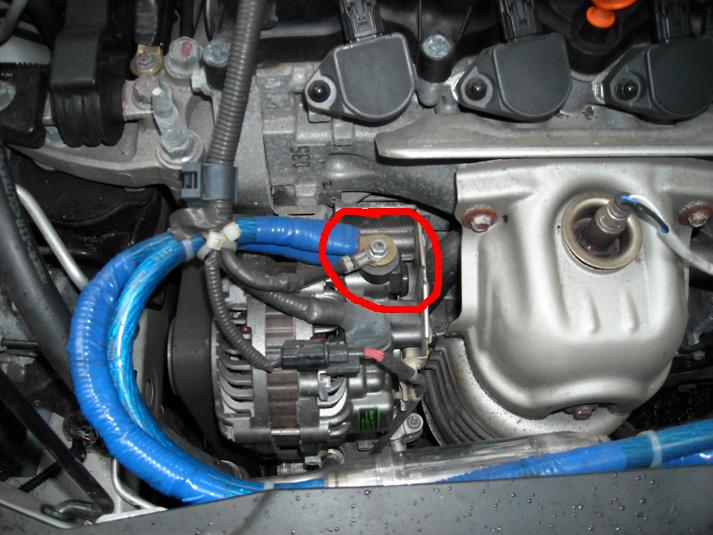
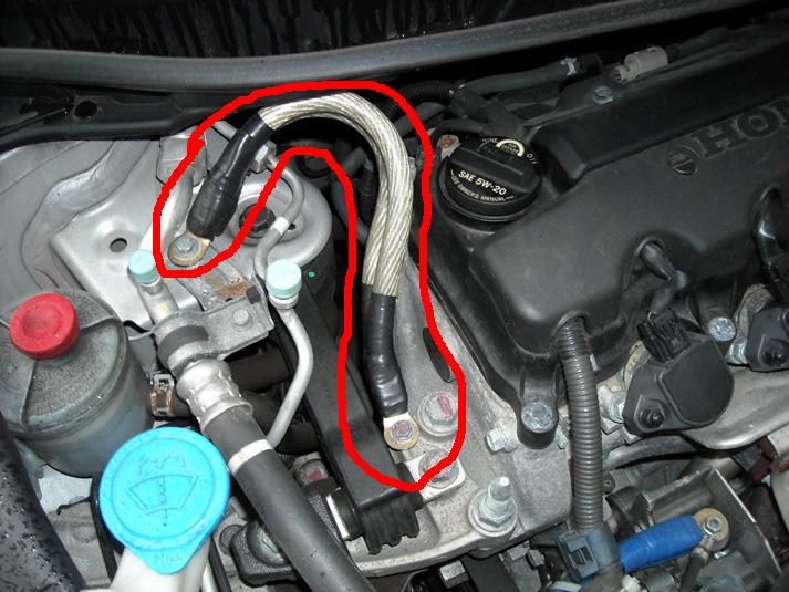
First, the alternator lug - notice the factory wire still attached. The tape and convoluted tubing on the wire is to avoid wearing through the wire jacket in areas where they rub something in the engine compartment.
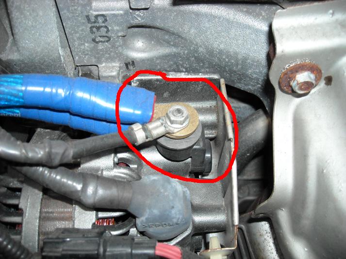
A close up of the alternator lug to show where to trim the plastic:
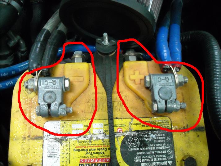
Next, the battery terminals. Positive has a +, Negative has a - . Their location and which side is which will differ depending on the battery. This particular battery is a dual post group 34/78 model - meaning it has both top and side posts for connections:
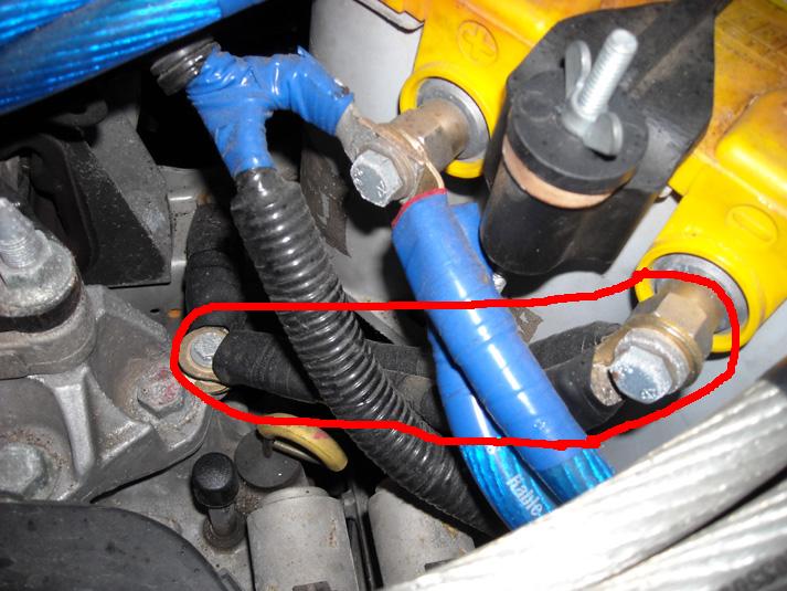
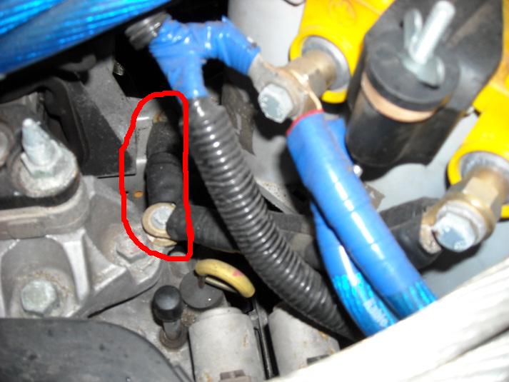
Here is the wire from the negative battery terminal to the engine block. In this case, I actually used the mount which goes to the trans bellhousing - but the bellhousing bolts directly to the engine block. I used the side posts for the big three wiring - they made things easier with the 4 runs of 1/0 going to the rear battery already on the top posts:
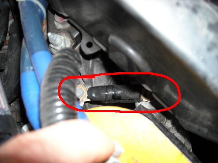
From there, a short jumper to the "framerail" of the unibody. Make sure to remove the paint from the ground point on the chassis:
A top view of the block to chassis jumper wire:
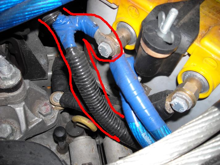
The factory positive wire should be retained, and needs to be connected to the battery somehow. I removed the red plastic protective covering, and unbolted the wire at the ring terminal beneath it. Then I trimmed the factory ring terminal and connected it to the side post of the battery positive. Threre are various places where the factory wire clips into bracketry, you may need to remove these clips and re-route the wire, depending on your battery and terminals.
I also replaced and re-routed the factory ground strap on the passenger side. This technically isn't a necessary part of the big three, but I included it nonetheless.
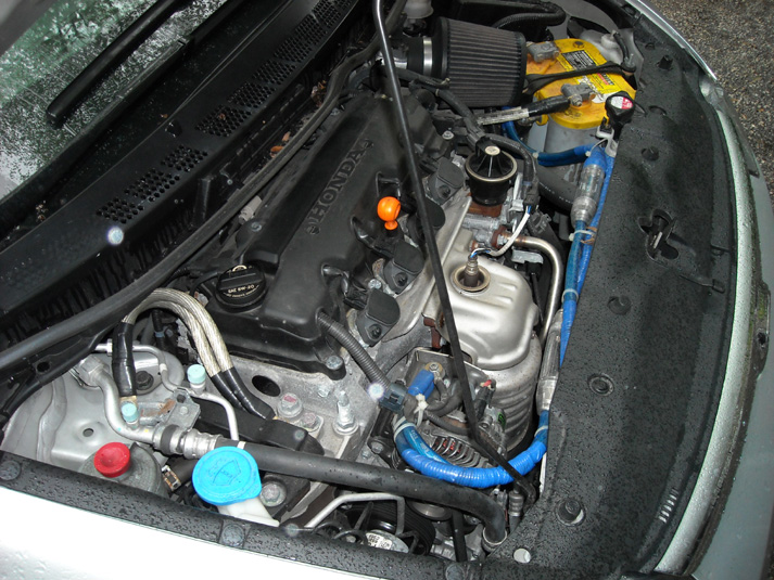
Finally, Here's a view of the entire engine bay, to show you how I routed the positive wire between the alternator and battery positive. I went above the radiator on radiator support. I drilled some holes in the support, and use zip ties to keep the wires in place. You can also see the clear ANL fuse holders (Each holding a 300 Amp fuse) on the positive wires. Just be sure to keep the wires off of the exhuast manifold on the front of the engine.