Cold Ram Air Intake Scoop 14-15' Si Coupe

Darkout

Supporting Member
VIP Member
1,107
807
Cocoa, FL
Vehicle Model
Civic Si
Body Style
Coupe
Alright so I've been searching the internet for awhile on random things and came across an interesting set of videos that I figured i would share with you.


The info may be already known by most but i found them to be great watches if you have time, I personally learned a handful.

Now at around 23 min or so in Tech Talk 1, Banks talks about how he achieved higher Intake Density (ID) by a simple cold ram air intake duct. My brain started to turn from here on as i watched all 3 videos.

Do YOU think a cold ram scoop on the civic while using the FACTORY air box is worth it?
I personally think it would be the most beneficial mod we could do to an already top preforming intake vs aftermarket as been proven.

So how can i make this possible...my first thought was right to the drivers fog light garnish. I was a little lost at this point on how this could be possible since i haven't dug into the car personally. A few days go by and then i stumbled upon the DIY for the resonator delete and i see how doable this actually could be.
http://9thcivic.com/forum/threads/resonator-delete-si-sedan.4811/ (the DIY if you dont know what your looking at here)
8_G.jpg

The opening left after the resonator delete is more than sufficient to fabricate a scoop to feed into the intake tube.
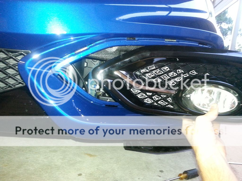
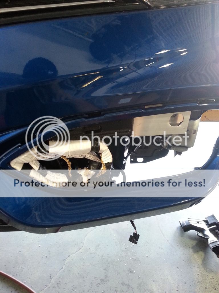
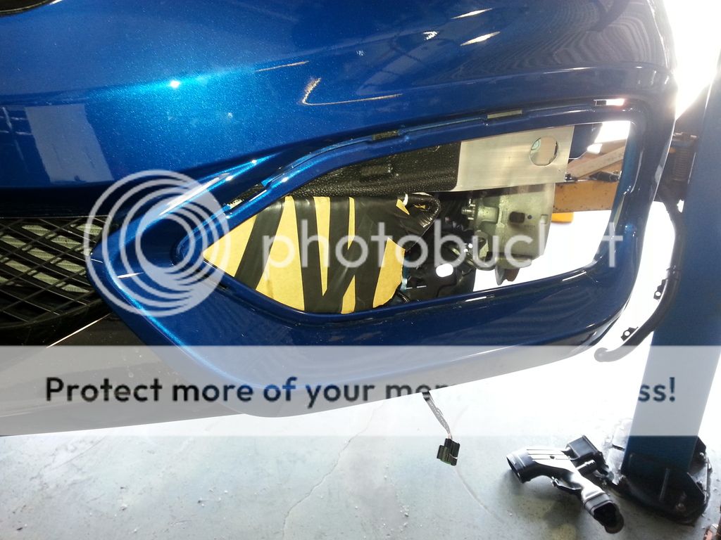
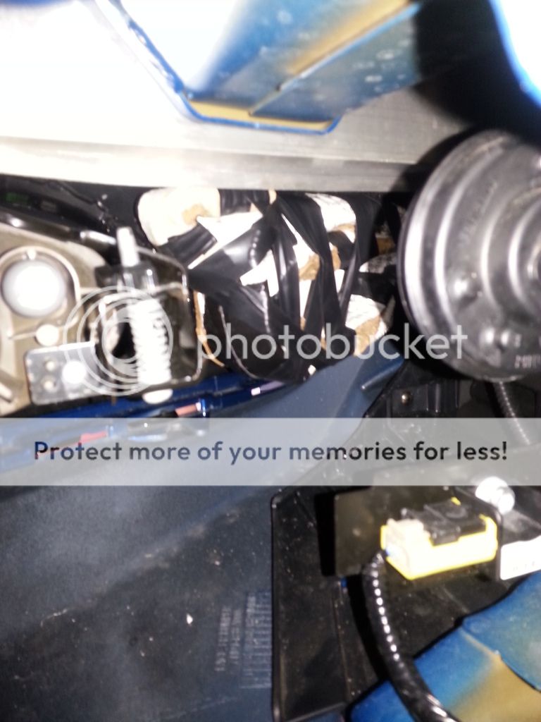
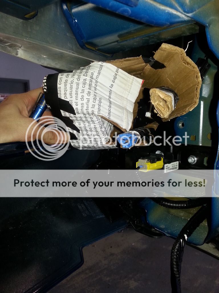
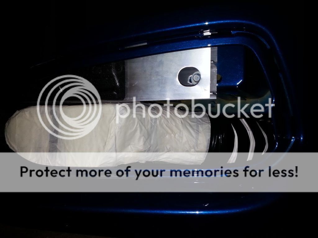
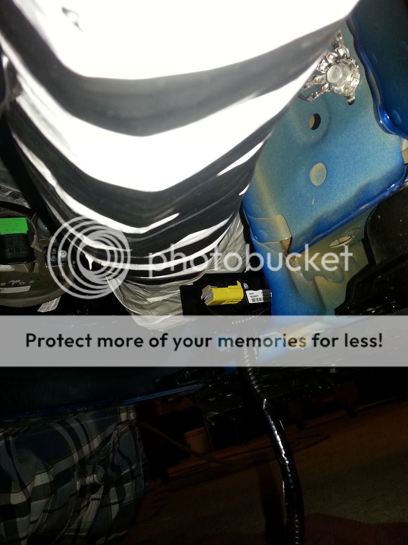
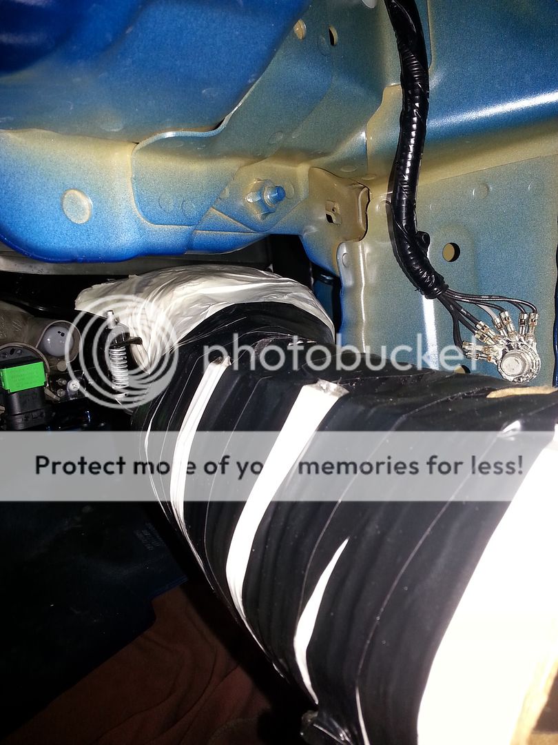
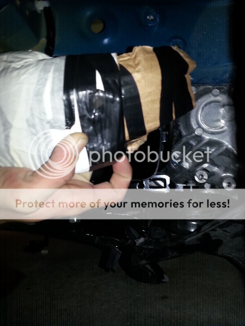
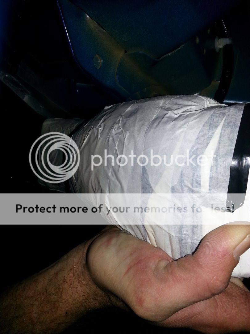
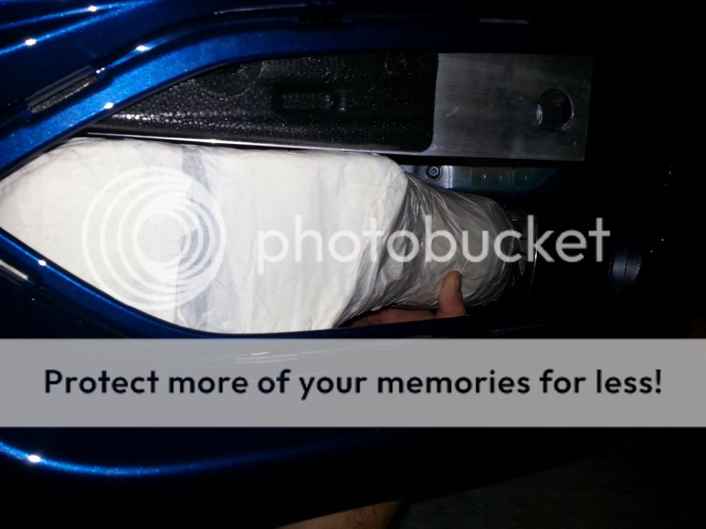
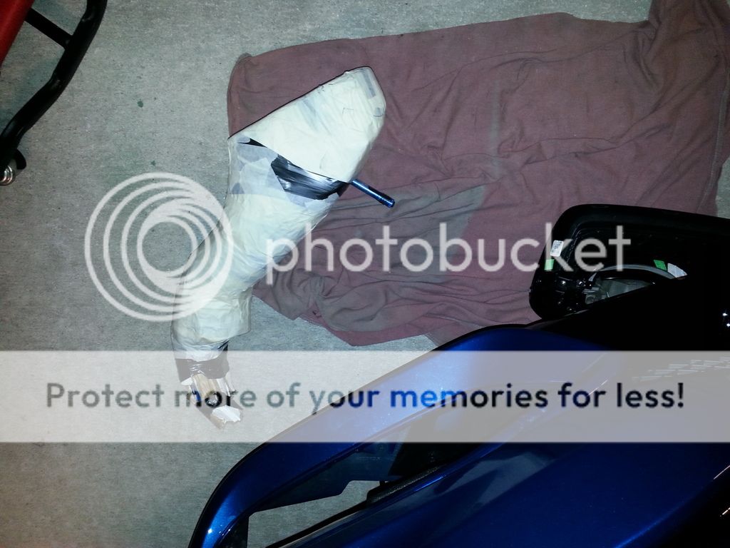
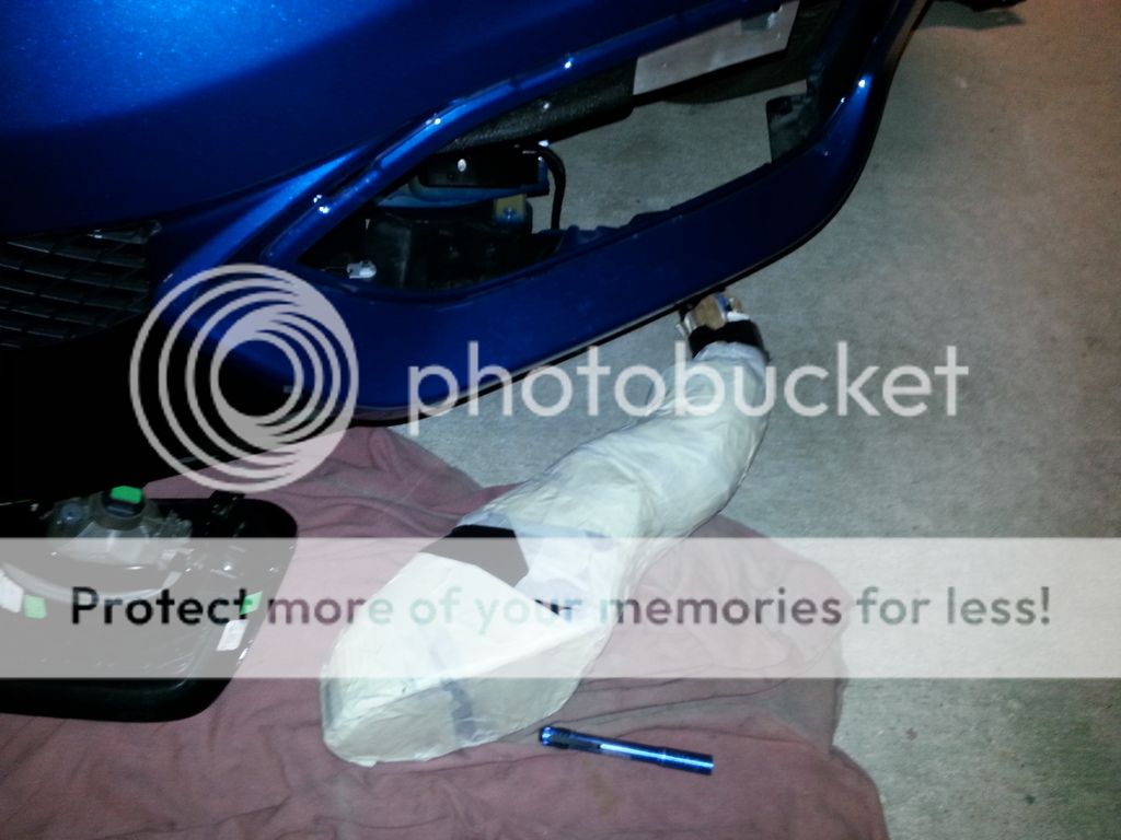
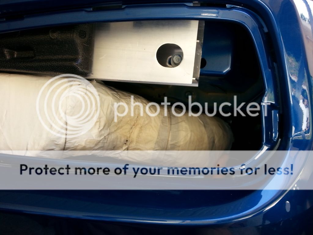
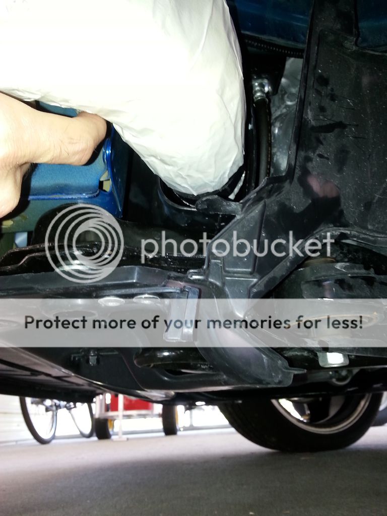
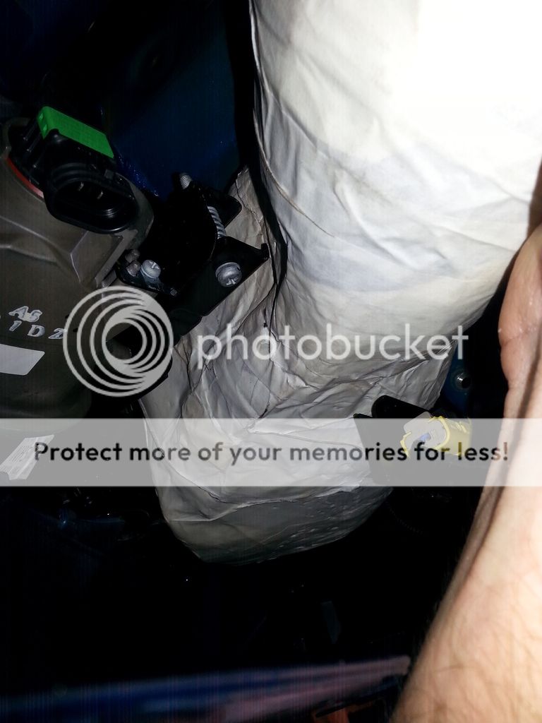
Below are a few pics of my Coupe with the garnish removed. You can see where my resonator is still installed which is where the scoop will route to as seen above.
20150508_195841_zpsaoymn31p.jpg
20150508_195827_zpsnuzy3kxh.jpg

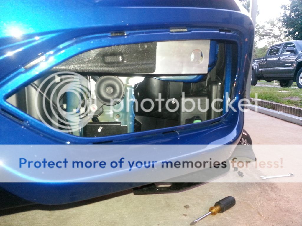
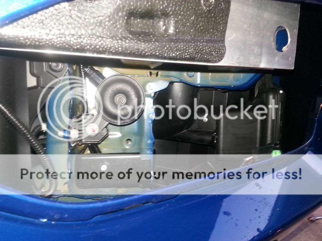
Off the bat i noticed that the horn WILL need to removed completely or relocated one way or another as it is in the way. Hard to tell from the picture but a smooth design is not possible with the horn there. The other "problem" is the aluminium crash bar that obviously limits the scoop opening. I still feel there to be more than enough room to still allow good ram air.
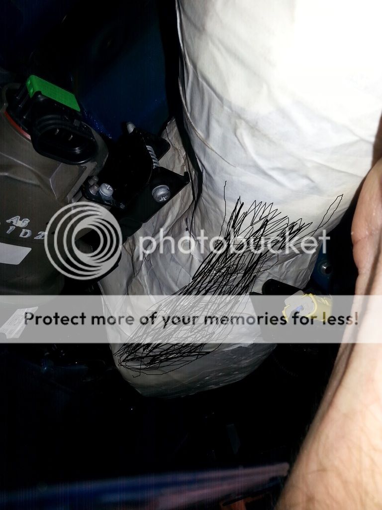
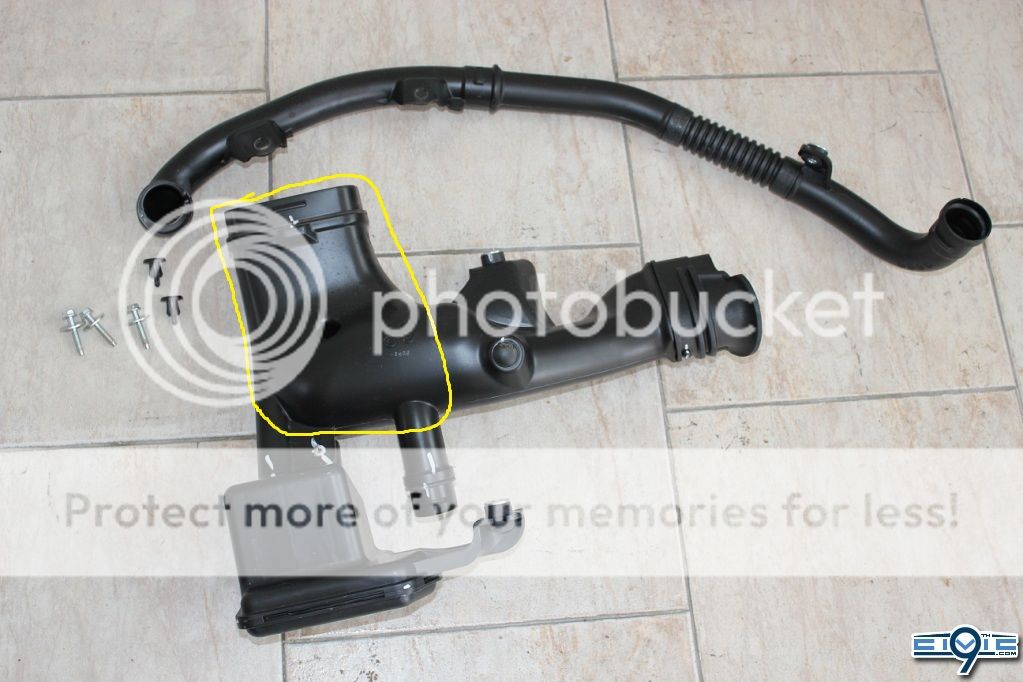
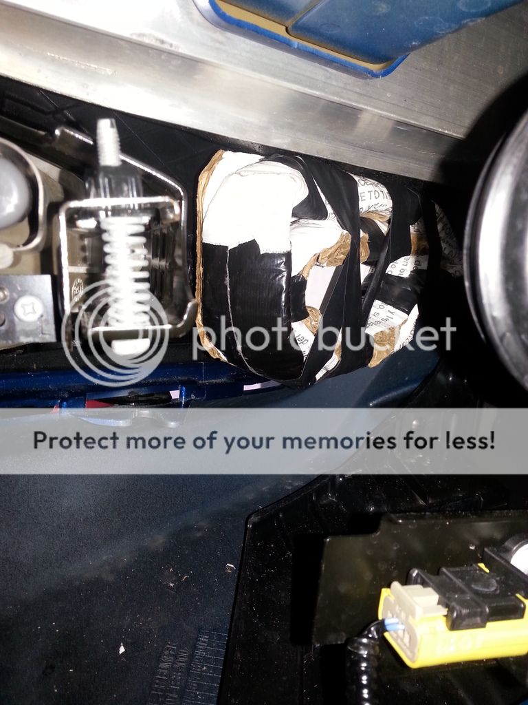
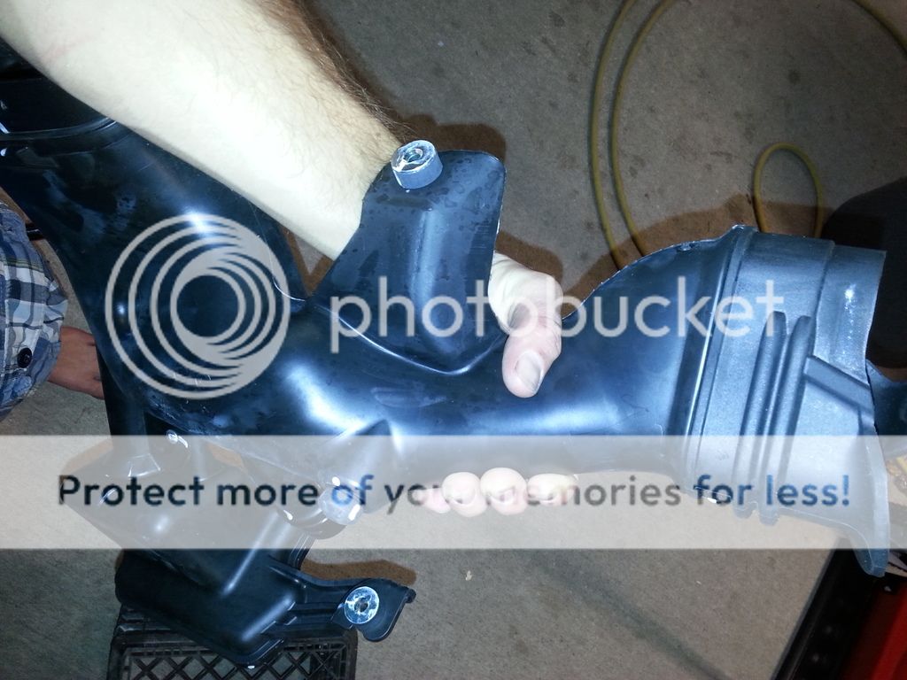
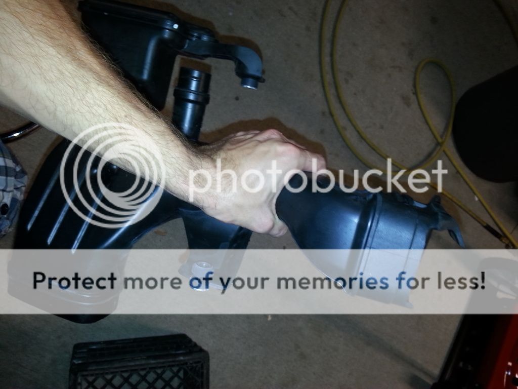
I was also thinking of using my (or if i could buy someones off them:D) resonator piping that you remove in doing the delete so the connection to the intake tube is sealed as well as a good base to build the scoop off of. Ideal portion is circled below
res_zpsrxuhrcun.jpg

My next obstacle is modifying the drivers fog light garnish. I'm gonna order one from @CollegeHillsHonda so i don't screw up my original one if i make a mistake or decide to scrap the idea at some point. Gotta support the vendors!
The modification to the bezel is basically cutting out an opening to allow air to actually flow around the fog light. My thought is to just cut out each diamond in the pattern but leave the "cage" look to it. Example below
20150508_200014_zps1mjiavx0.jpg

The exact amount and which ones i would need to cut would be determined but you get the idea. i would then put a screen lining behind it to keep it from a bug/debris ram.
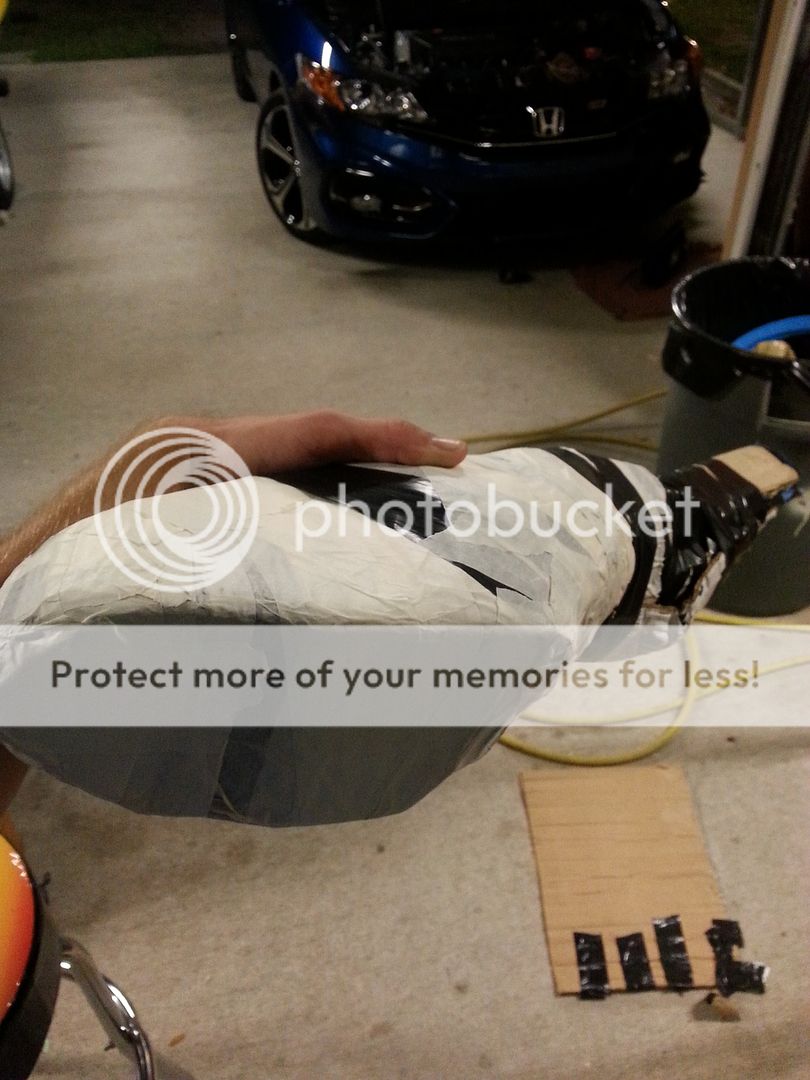
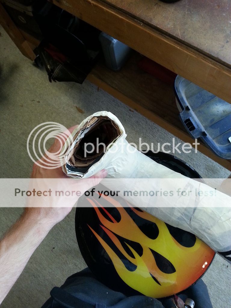
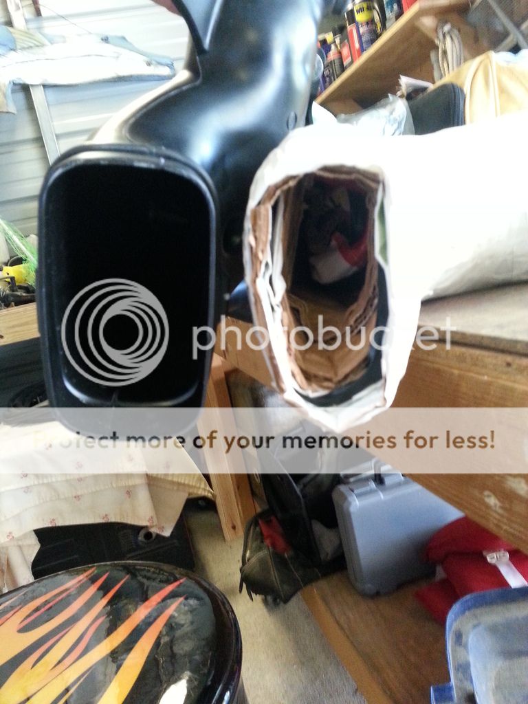
The last problem that i had to figure out to start making this idea a tangible outcome was the material to use. I'm still not 100% as I'm open to any and all ideas if you think of something better BUT i was leaning towards something like this...

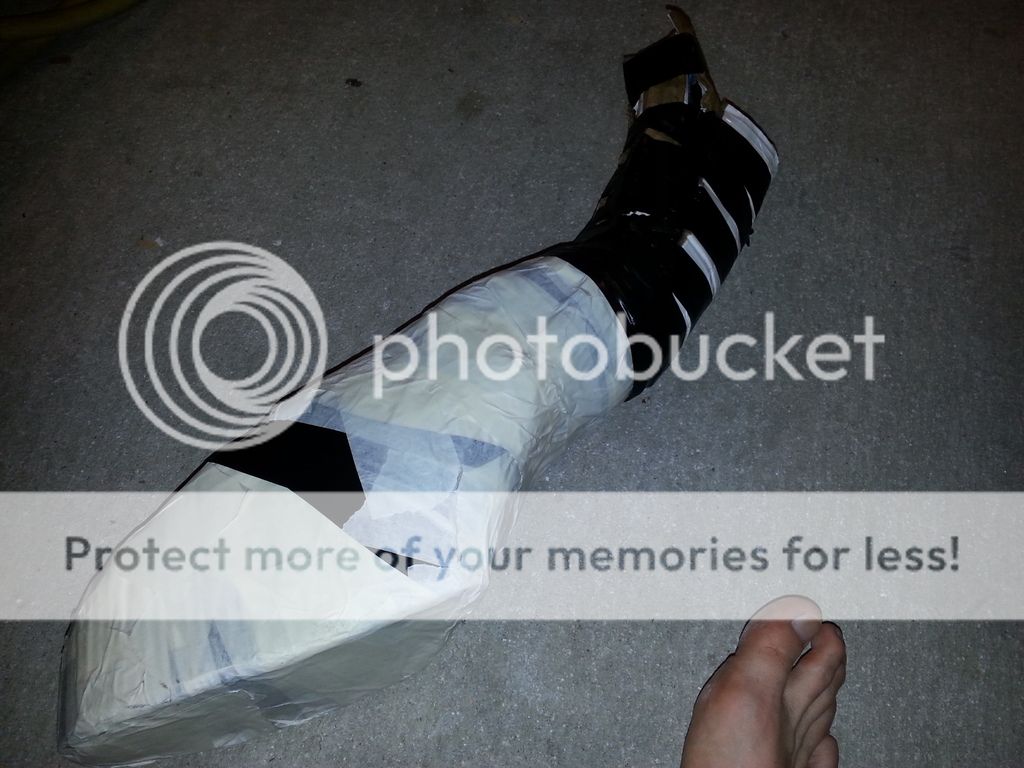
My idea is to build a balsa wood/fiberglass duct. Seems plenty strong enough for vibrations, won't absorb water, relatively inexpensive(guessing as i have not looked up material prices yet).

I'm not sure if this has been thought of or attempted yet but i LOVE trying new DIY mods and building things with my hands so I'm determined to make this possible. Figured i would share my random and crazy idea and welcome any thoughts/criticism that could help this be productive.
 
Last edited:
The gains "in my mind" would be that of any aftermarket CAI. (Could even maybe adapt a formed scoop to a CAI that sits the filter in the wheel well) The purpose allows ram air during driving to allow the intake to gain slightly higher Intake Density thus allowing more power. This will not be felt sitting at idle or slower speeds but as speeds increase so does ram air. The ram air might cause a slight pressure in the intake maybe 1-1.5psi max when at higher speeds. On top of that, the intake will be getting the coolest charge of air possible and we all know heat is number one enemy for air density. As taught in the videos, "boost" with a turbo or SC is just creating a higher Intake Density to allow for more fuel, thus more power. ID would practically stay the same if the charge air temp was not cooled by an intercooler in these setups. I'm just trying to apply simple concepts that have been proven to work in the past.
Reading through some of the posts on the 8th forum I noticed a lot of people tapping into the cowling to get the low pressure forming at the base of the windshield. Lower pressure, lower temps and semi ram effect. There is also a low pressure created towards the bottom half of the front bumper which is what I want to tap into by going through the fog light garnish.

I don't feel your knocking it but inquiring info on my thought process.:confuzzled: I'm not too sure it's going to be worth it myself BUT thats where the fun for me is. Creating a custom mod and learning.
 
If you search the 8th gen forums for the "icebox" intake mod I believe this is a very similar thing you are trying to do. I think it would definitely be worth attempting.

The stock air box flows very well on its own. The high filter location will help reduce the risk of hydrolock. People who did this mod also removed all the "vanes" on the inside of the stock box to help the air move better. Basically, smooth out as much of the interior as you can. I have not seen the inside of a 9th gen air box lid so I'm just guessing at it. The HPS intake tube replacement that is smooth silicone instead of the ribbed stock plastic might be worth looking at in addition to this as well.


EDIT: Don't remove the horn completely. Just relocate it. You might need it and it would be bad not to have it.
 
Now your thinking along the line that i am Nix! Thanks to @webby and reading posts on the 8th forum i see that this idea is well worth it. I'm building a scale model of my idea tonight.

I don't plan on removing the horn, ill splice an extension if needed to relocate it wherever i need.
 
Well my scale model is probably the most basic thing you could make but during the process I brain stormed some great ideas on how I'm going to make my "final" design. Nothing's final till its actually done lol and i might be able to replicate the design if i plan according just in case anyone else is interested.

I started with a crude outline of the fog light garnish.
20150509_181720_zpsbw2ocrmf.jpg


Added a few sides
20150509_185733_zpsw9kxlbfl.jpg


And then a few more
20150509_193038_zps02w2aywr.jpg

20150509_200647_zpsiptjxa8e.jpg


And it finally looks like this
20150509_205216_zpsaaaqdq1e.jpg

20150509_210651_zpshvrsgac2.jpg


Thus you get my basic idea. Very crude and probably worthless but it did help me move onto my next step to mock up an actual size scoop.
 
I was thinking of doing this to my car. I did this for my r18 it was easier cuz the box was set up as a scoop already. The SI is jus little different.
 
Being a slow day at work today i was able to get the car in the shop and on the lift all day. Got some pics and a cardboard mock in the beginning stages done. I'll upload the pics and descriptions later tonight when i get a chance. Looking promising just gonna be a long road traveled for what i have planned:banghead:
 
  • Like
Reactions: Nix
So after mom's day dinner and festivities i can post up my progress i made from today.

Let's start with the slooooooooww day allowing me to do a res delete/tire rotation(at 2200, the fronts see hell every day:flame:
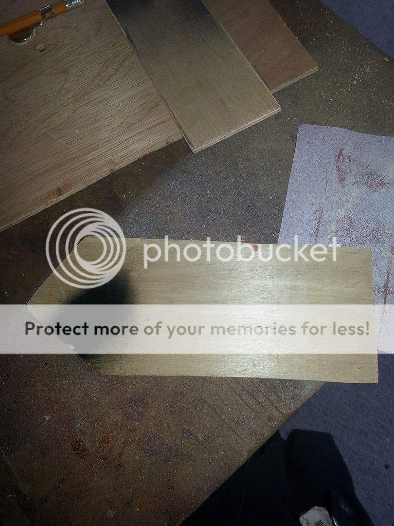
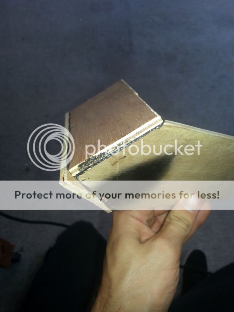
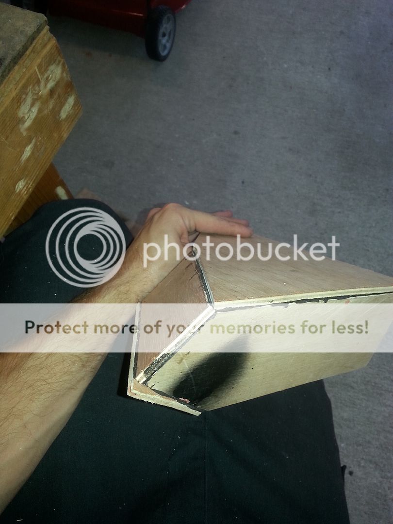
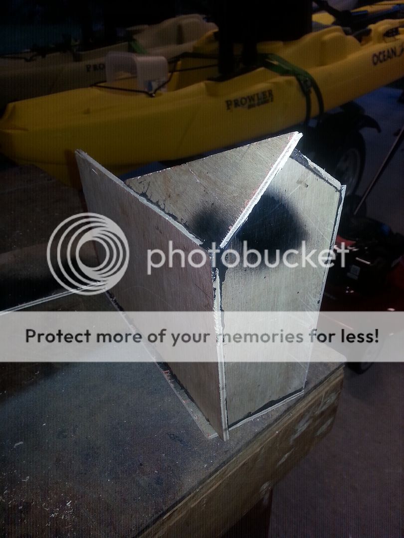
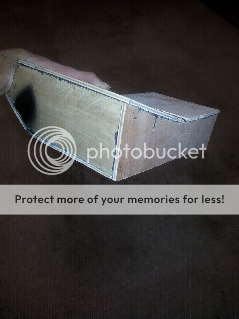
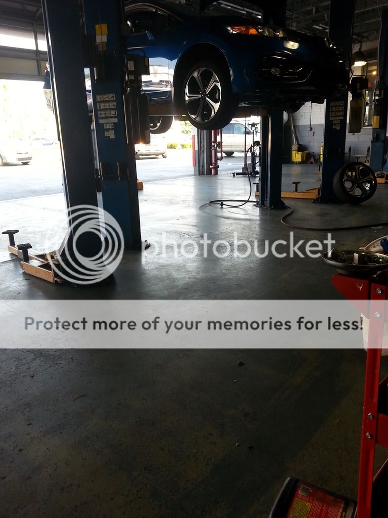
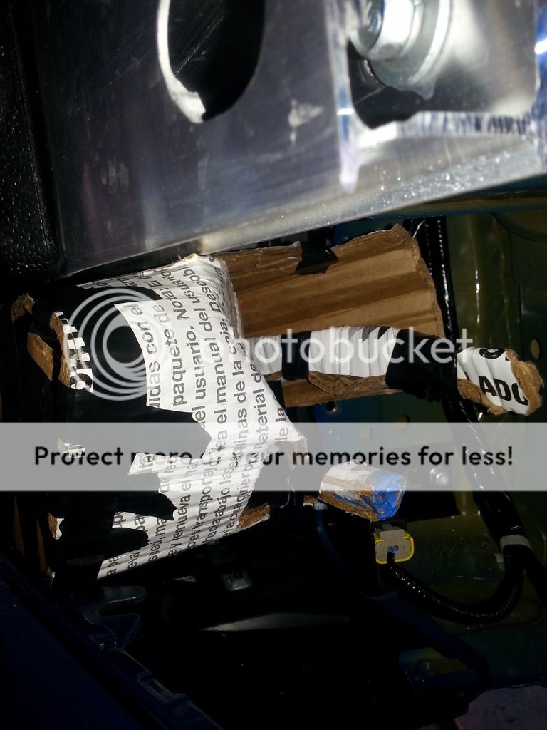
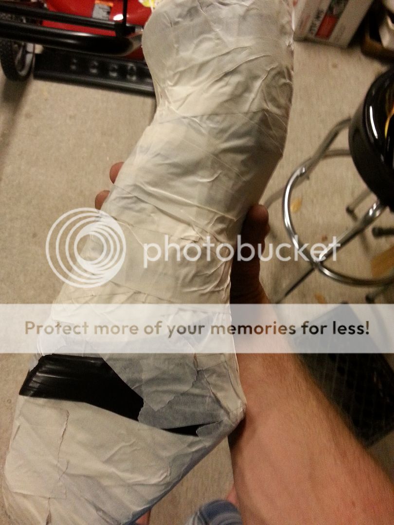
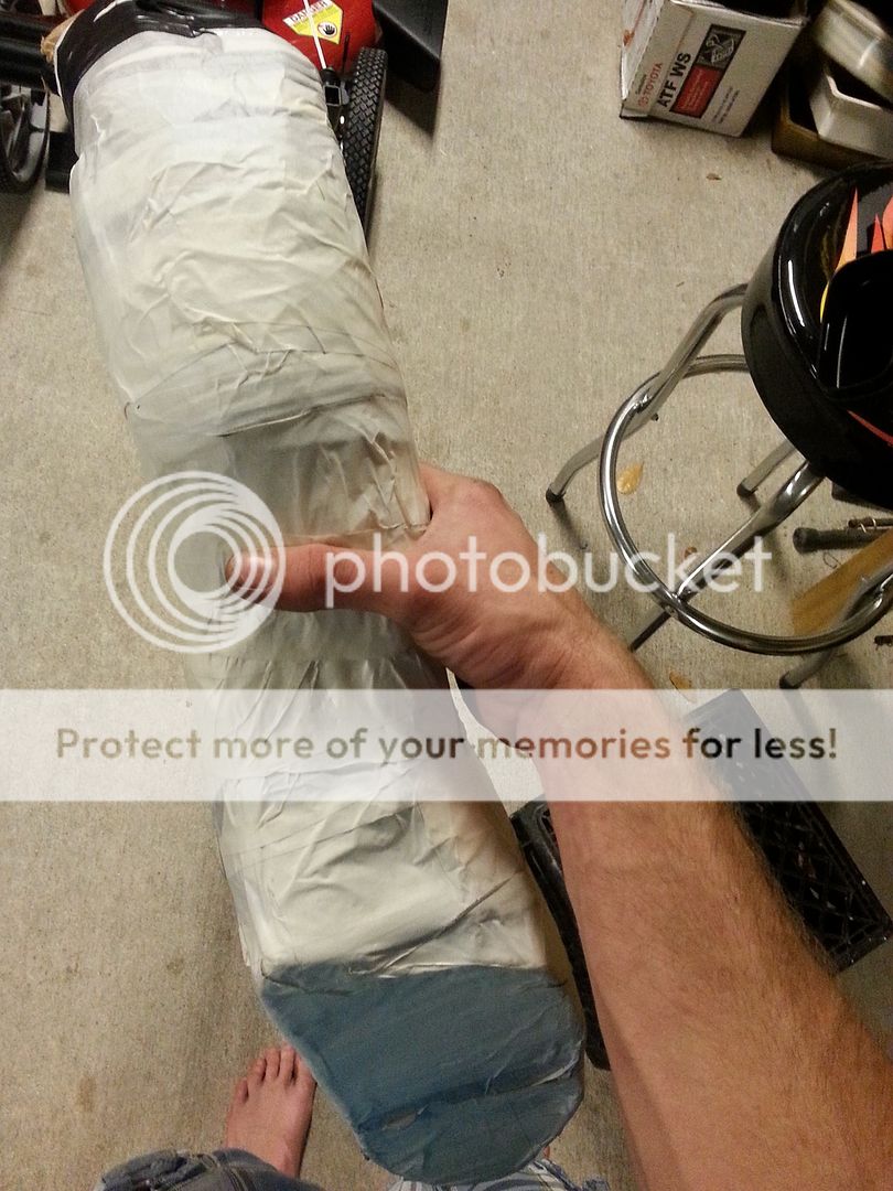
) and my first attempt at a mock up. I was the only one in the shop at this time. *Side note* HOLLY HEAVY BATMAN! My 99 jeep grand cherokee had lighter rim/tire package from factory. Why do manufactures go this route now
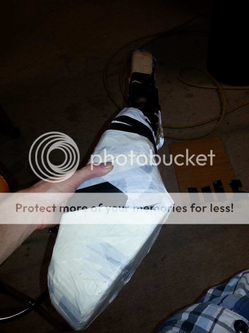
:pat:
20150510_094204_zps7cwrqbiq.jpg


So after i'm done face palming I removed my resonator and began to mock up the induction scoop. Having time on the lift and being able to see things easier and clearer with my wheel removed i noticed that my original idea of "scooping" the whole fog light garnish is no going to be ideal. The design i am leaning towards is using the area i whited out in my previous post.

I'm using cardboard to make a "formed model" it's stiff enough when need be as well as becoming flexible when worked prior to molding. I plan on making a solid inner mold that i can make 2 half's of a fiberglass mold by forming around it. Ill then be able to make repeatable half's out of the two molds, that i can form together and thus making a one piece fiberglass scoop. Best part is if/when i complete this and if it shows to be a functional gain, ill be able to replicate it with my existing molds to share to other 9th users :thumbsup:
20150510_121159_zpsvszhwiau.jpg

I used strips of cardboard here(above) rolled in a tube shape then formed into the "pentagon" shape that i need.
I then cut a flat shape out to tape to the front of the "tube" section to keep the shape(below) as well as adding a small "tail" to the top right to fill in an area that I'm using/maximizing the surface area i have to work with.
20150510_122541_zpsy6vg4zv1.jpg

Here's a few pics of what it loos like from behind the bumper with the fog light garnish "in place" (first pic is with out the added "tail", second pic includes it)
20150510_122016_zps2icu3mei.jpg

20150510_122524_zpswfuuiooi.jpg

I then wrapped my front fascia piece to give the mold a shape and add some "tubes/sections" to start froming the shape towards the wheel well in front of the "place where the horn was." You can see the horn in the pic above but removed it in the ones below. You can see how crucial it is to relocate it.
20150510_134927_zpslhghzibg.jpg

20150510_134937_zps5itcdlq1.jpg

I made it slightly further in shaping my mold before i had to button it all up and attend to beer thirty. Can't make that wait lol:beer:

Now the other issue i came across that kinda makes the intake design less open is the front crash impact sensor. You can see it in the previous three pics. It's under the horn with the yellow clip. This will NOT BE TOUCHED! It shouldn't pose an issue as far as maintaining a good flow design but really sucks cause without it you could make the scoop design much simpler and easier. BUT i knew this wasn't going to be easy in anyway so it'll be overcome.

I worked on this probably 3-4 hours today and even though it may not seem like a lot, i feel i made a nice advancement today in the right direction.

What do you all think so far?
 
  • Like
Reactions: Nix
:beer:After many of these and several hours i managed to wash/wax (as i do every week) and make progress on my mock up/mold. I don't think most of anyone could see my vision with the previous photos but maybe it will be a little clearer now. Unfortunately my phone was dead(the only thing i use to take pics) when i first started tonight so i couldn't take a pic of what i finished with at my shop. Either way let me just put a little list of pics so you all can follow along :D
20150513_231930_zpsgy2l9aee.jpg

20150513_231942_zps8j7nsyvo.jpg

I'm thinking of using this next one as my foot model pic :eyebrows:
20150513_235654_zpsji05aaq8.jpg

20150513_235612_zpst3zixsx8.jpg

The 2 pics below have the mold sagging down I'm pretty sure but you get the idea.
20150513_235537_zpsinuswpji.jpg

20150513_235526_zpsv4vjhjwi.jpg

You can see a small amount of the intake opening after the resonator delete in the next one. The length is about there, just need to make the turn.
20150514_001120_zpszhmbdmjc.jpg

20150514_001134_zps4jxufkdp.jpg

20150514_001155_zps5cfnttjx.jpg

20150514_001238_zps1264qs5a.jpg

20150514_001254_zpskj0augqx.jpg


So far it's looking like my mold is going to give better airflow all the way around vs the stock resonator/tube inlet that you remove as is said to be a good flowing design.

This is the smallest diameter on the stock pipe that i could tell. The visual comparison is my hand.
20150514_004013_zpsi0vfksk8.jpg

20150514_004020_zps59d2wjqa.jpg


I'm not the far from touching my fingers together.

This is the smallest restriction on my design that i can tell so far. My hand as the comparison

20150514_004219_zpsb0nqhxkz.jpg

20150514_004225_zpsr19o18ln.jpg


It's a tight fit inside the bumper and will need some shaving once i get the full mold shaped, but the progress is going extremely well. :dance::bananasplit::dance1::cheerleader::pianodance::dogdance::domokundance::lock::pinkdomokundance::rockwoot:Happy Times!
 
  • Like
Reactions: Nix
Nice progress. Maybe I missed it, but, what are you making the final product out of?
 
You didn't miss it, I hadn't fully decided but I'm pretty sure its going to be fiberglass now. It's going to be the easiest to form fit it as I'm sure it will take a few tries to get my perfection touches on it and have it as smooth as i can. I think this will also allow me to make the process repeatable and fast once I make the final molds. I'll have to figure out thickness vs strength vs weight but i don't think it'll be much of a weight issue.
 
Make the fiberglass thin-ish then add a layer of CF. Style points and strength!

:giggle:

Have you thought about doing just a small scoop then attaching somekind of "hose" to it, to then connect to the stock tubing going up to the box?

"hose" could be brake duct hose or something similar? I know it wouldn't look as good but def would be a bit easier to work with.
 
I've thought about a carbon fiber design on it lol and I have thought about using preformed pieces and such but I like the uniqueness of what I'm doing. I'm wanting it to be a 1 piece component. Plus i think the real smooth design at the catch point would help increase air flow into the air box. There is one other portion of the intake tubing into the air box that i want to fix with fiberglass (portion that reseeds in to allow space for the coolant line) but not sure if the heat would cause an issue to the fiberglass. I wouldn't think so but I don't mess with the stuff enough to know
 
So i think I'm about 90% done with my mock up and ready to make my first attempt at the fiberglass moldings. I got the shape done up to the point of connecting it to the factory piping, the oval isn't the correct shape but all the bends I feel are close enough. I think i ended up using 4 rolls of electrical tape and 2 rolls of masking tape (and not done yet) to get to the point I'm at now. :rotfl: 
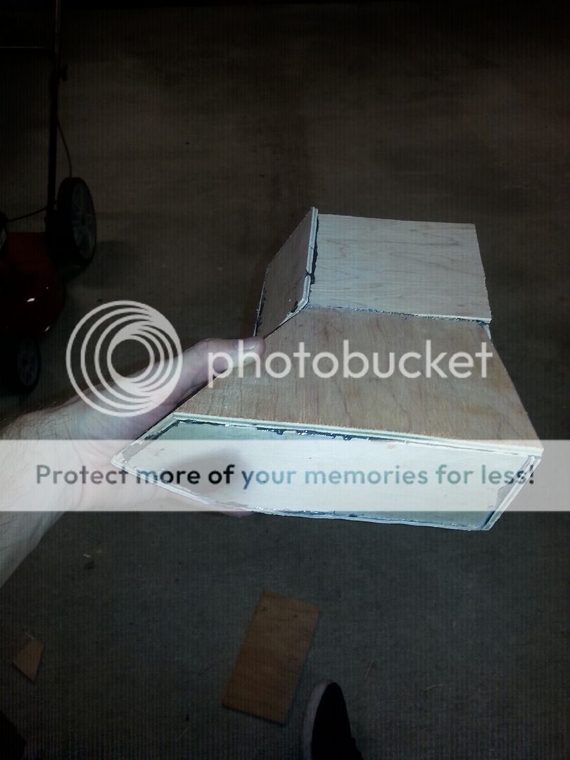
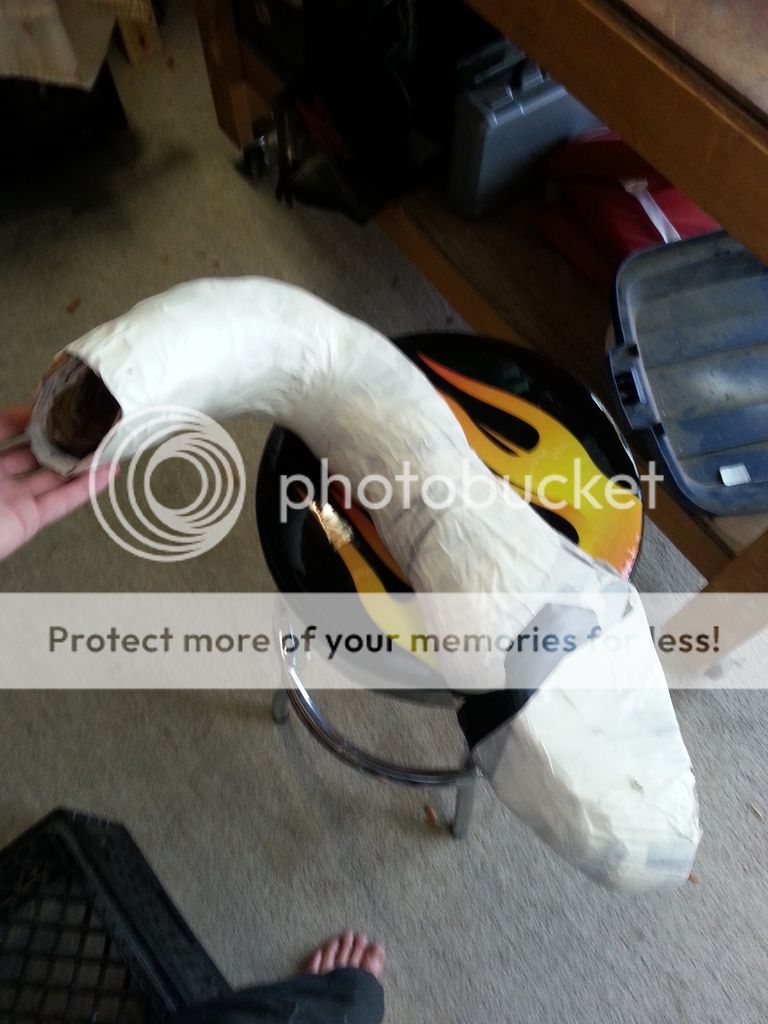
I'm debating to modify the front scoop with a lower channel to increase amount of captured air flow, i'll try to mark what I'm talking about.
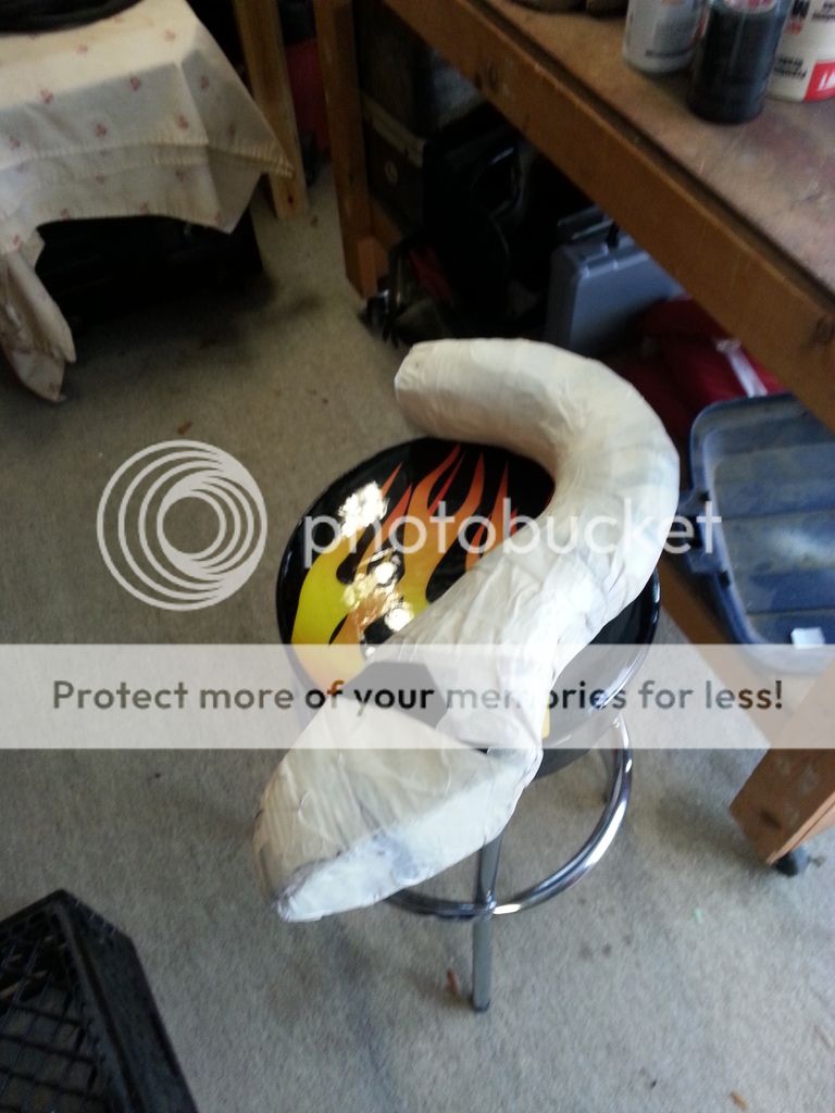
So this is the final shape i came up with
20150514_150336_zpsd6tnftsy.jpg

20150514_150350_zps7easbgx4.jpg

20150514_150439_zpszjugemu0.jpg


Here's a comparison of the stock opening vs my shape (not done)
20150514_150701_zpsynfknwns.jpg


It clears about 90% of anything it contacts, which should be taken care of when shaving the fiberglass mold for perfect fitment/design.
20150514_142700_zpsid2ekv0a.jpg

20150514_142746_zpsh0enhj8o.jpg


Hard to tell from the angle but it does clear the crash bar sensor bracket and the fog light bracket.
20150514_142938_zpswwkpkhad.jpg


The pic above also has the fog light garnish completely installed. Everything is easily removable once installed which i thought the scoop might cause issues once installed but it doesn't.

From this point on i plan on wrapping my entire mock in fiberglass and once dry cut it in half. This will give me my two half's of the first "crude" mold i could replicate it from.

Getting excited:hyper: lol
 
Oh and the crappy done shaded area is the channel I'm thinking about adding since that point seems to be the most restrictive part seeing as it hugs the fog light and crash bar sensor bracket.

20150514_142938%20mod_zpsgqasrfbc.jpg
 
This is looking great! fiberglass would be a good starting point. Light weight and easy to form. Hydro lock is my only concern. would be very interesting to see final product with a tune to compare with current CAIs on the market for our cars
 
Back
Top