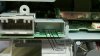
If your nav unit does not have the F connections you will have to take off the back and solder the camera wires here the Camera bit 1 wire "blue" goes to B15 Camera Bit 0 wire "Green" goes to b4 the others goes as in picture
I still have to buy the cam best I can find it for is 160$ was hope when the model is out a little longer they will come down. Here some you might like complete 2012 civic spec from cam lobe height to ring groove gap
It'll be interesting if the 2012 Navigation equipped Civic works the same way as the i-mid does when adding a camera. The i-mid software is already programmed to work with cameras despite the lack of an option on the 2012. If adding the camera to the navigation unit doesn't work you could try adding it to the i-mid screen instead.
I thought it might be the B and J connectors on the navigation unit, but your other photo indicates that the camera connects to the B and F connectors. All the pin numbers and colors line up correctly with B and F so I'm just assuming it's an error on the schematic.
Yea, had to be a mix up as you see they called F what should be J the RDS ant. unless at the last second they changed them but It would not change the wiring
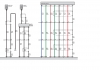
I just did a lot of cross referencing between all of the files that were uploaded! The pin outs for the cameras for both navigation and the non navigation cameras are all jacked up. Here is the revised document for wiring into the navigation system that Dallas Ray posted. If this doesn't work we should be able to wire this into the I-MID. This alternate option would be the same way as the 2012 CRV is wired and get output on the I-MID instead. Personally I would rather insert several pins into my I-MID than risk soldering wires to the navigation system unit.
The multi-view cameras will require seven wires and one shield back to the camera. This can easily be accomplished by using CAT 5 shielded networking cable. The blue bit 1 and green bit 0 are shown as two separate wires that are ran outside the shielded cable. Then pin B9 is connected to the reverse light circuit under the dashboard.
Jasonandre how many connectors are going into the back of the camera you purchased? The standard camera has a six pin connector with six wires. Although I found that only four wires go into the back of the camera. I used a multi-meter to trace the wires at each end of the pig tale wire that came off of the back of the camera. I have six wires that include a red, yellow, two white, and two black wires at the connector. The two white and two black wires merge when they get to the back of the camera. The diagram below is a guess at what each of the wires purposes is. I have based the descriptions off of the colors from the incorrect multi-view and standard camera diagrams. I do know that the standard and multi-view cameras colored wires' functions are identical and that I see that the functions of the colored wires' functions have changed from what was used in the 2012 CRV camera.
I drew up a diagram for standard camera connections at the i-mid connector. The names and pin outs are correct. However I don't know yet if the colors are correct.
Now that we have a multi-view camera it would be interesting if someone could test if it would work in the non navigation models through the i-mid like the 2012 CRV does. The select button on the radio changes the camera views in the CRV. The diagram below is not for the multiview camera. It is similar but is missing a couple of wires that are only present in the multi-view camera.
Here is the diagram for multi-view camera connections at the i-mid connector. The names and pin outs are correct. However I don't know yet if the colors are correct.
On nav unit b9 is all ready there for back_lt the brown wire even on 2012, You don't need the shield wires and you can power the cam from the reverse lights in the back. I would rather have mine on the Nav unit an I have no problems soldering few wire and depending on when yours was released you may even have the F connecter