AlienPrime
Well-Known Member
Disclaimer
9thcivic.com may or may not endorse various DIY projects, all DIY projects are purely "at your own risk". If you are at all uncomfortable or inexperienced working on vehicles (especially electronics and mechanical), please reconsider doing the job yourself. It is possible on any DIY to damage your car, void your factory warranty, disable a safety feature, create a hazardous condition, or harm or even kill yourself or others. Examples would be the vehicle failing on you, getting an electric shock, or disabling an airbag etc.
Your dealer or mechanic, or professional audio shop may provide services (and a warranty) for any DIY job posted on these forums. Sometimes, it’s just better to pay to have it done.
FAQs
Q: Is this DIY for all civics?
A: This DIY is for civics with iMids without Navigation. (Need confirmation on SIs)
Q: Whats the difference between Non-Si and Si iMids?
A: The SI's iMid screen display an additional info screen which is not confirm on which connector input is used
Q: Does this camera that you link us fit a sedan?
A: Yes, it will fit both Sedan and Coupe.
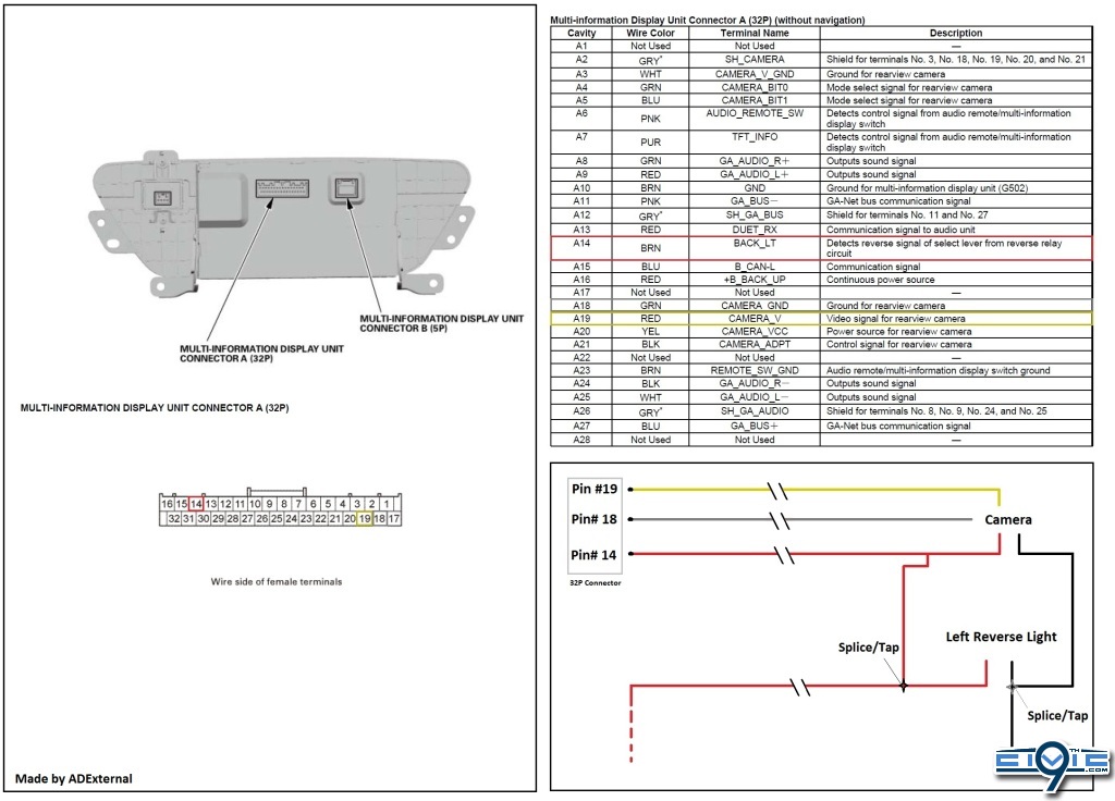
Q: Where are the pins to connect?
A: The pins to order is under Project Parts. They will be in the Prep-Work Instruction.
Q: Will I need a soldering iron or solder anything?
A: No, there will not be any soldering needed.
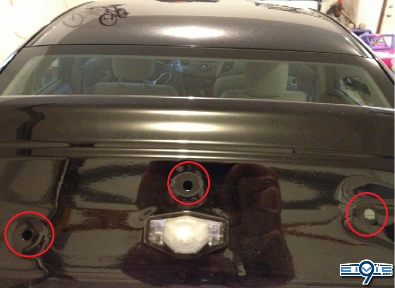
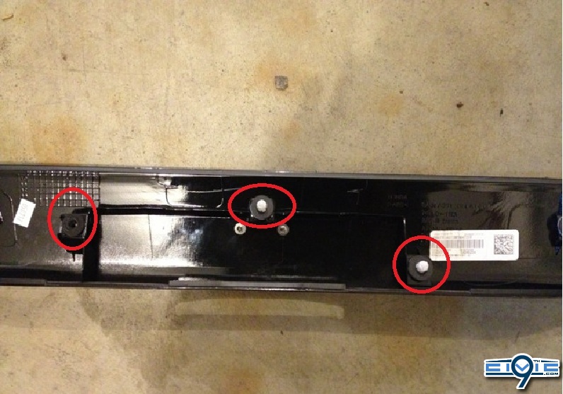
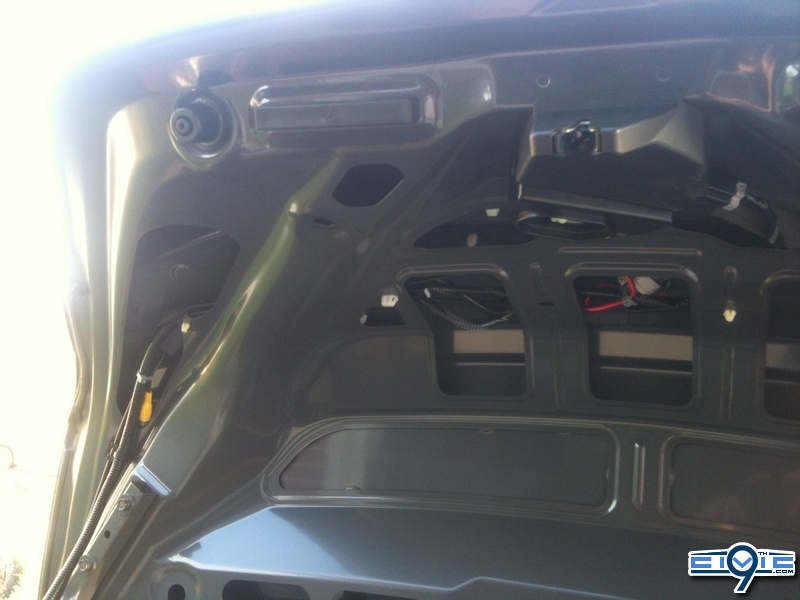
Q: Do I need to take off the rear deck lid on my Civic Sedan to remove the light cover?
A: Yes you do, instructions are under Sedan Models Only. This does not relevant to Coupes.
Q: How much did this project cost?
A: Depends on how much of the tools you have already. Order the requiring Parts will be about $33.
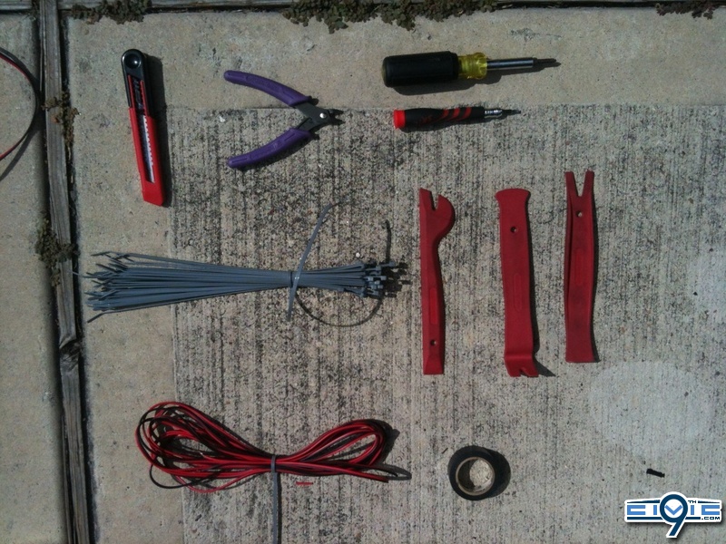
Tools
Required:
- Black / Electrical Tape
- 20 Zip ties
- Wire cutter
- Utility Knife
- Medium Phillips Screwdriver
- Small / Jewelers Flat-head Screwdriver
- Trim Removing Tools
- Extra wire or tug wire
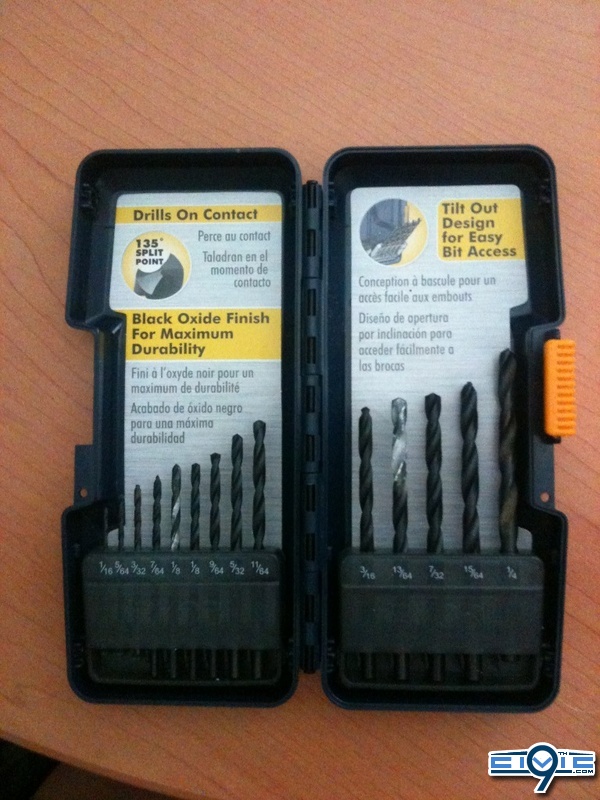
- Power Hand Drill
- Drill bits sizes 1/16 to 1/4

Recommended:
- Wire strippers
- Wire connectors (Marettes)
- Needle nose pliers
Project Parts
Required:
Reverse Camera -2012 Reverse CRV/CIVIC Back up Camera
Part Link - 7500K Xenon White LED CRV Fit 09 Civic Honda Car Mirror Rearview Camera P7512W | eBay
Cost: $19.00USD + Free Shipping
Shipping /Receiving Time: 7-15 business days
Comment(s): One of the issue I ran across as several other that when installed, the top of the camera view seems to cut off. So the linked one is one of the cheapest, has guide lines, and easiest to modify lower without getting to messy. There are several cameras on ebay that is similar to this one without guideline, whiter light, etc.
Note: When ordering, request 6000k LEDs
The original camera link is no longer available, but this seller has an active one with a similar model:
http://www.ebay.com/itm/Special-HONDA-CRV-FIT-2009-2012-CIVIC-Crosstour-Odyssey-Car-Backup-Camera-P7512L-/200884431596?pt=UK_In_Car_Technology&hash=item2ec5a52aec
Wire - 50ft 22 AWG Gauge Stranded Copper
Part Link - 50 ft 22 AWG Gauge Zip Wire Red Black Stranded Copper Power Ground | eBay
Cost: $9.92USD + Free Shipping
Shipping /Receiving Time: 3-7 business days
Comment(s): Any wire gauge from 20+/-2 (18-22) will work; Just make sure it is stranded to reduce wire heat and less surge. There is also plenty of cheaper one from overseas but I ordered from this seller several times.
Note:
Pins - White 12 SMD LED Car Interior Festoon Light Lamp Panel T10 Dome BA9S Adapter 12V
Part Link - White 12 SMD LED Car Interior Festoon Light Lamp Panel T10 Dome BA9S Adapter 12V | eBay
Cost: $2.49USD + Free Shipping
Shipping/Receiving Time: 7-15 business days
Comment(s): You will be taking apart the adapters for 4 of the pins
Note: You can use the dome adapter for the 12smd LED for rear dome lights.
Recommended:
Wire Tap – Posi-Tap
Part Link - Best Wire Tap Connector Posi Tap No Tools Strong Better Faster | eBay
Cost: $6.29USD + $6.00USD Shipping
Shipping /Receiving Time: 3-7 business days
Comment(s): This is not necessary to have but it will prevent you to cut or splice any wires so consider it as a fail-safe item. I recommend those who don’t work with wires often to purchase some sort of tap.
Note: Request the seller you want the red ones (18-24 gauged).
Note2: There are several different taps on ebay cheaper than this from $3.00USD - $7.00USD shipped. Just search wire tap and make sure it is red (18-24 gauged)
The wire taps (above) are not available, but I found a different style here (they also sell the 22 AWG dual conductor stranded wire):
http://www.lowes.com/pd_450934-37672-50054_0__?productId=4415289&Ntt=non splice wire connector&pl=1¤tURL=?Ntt=non+splice+wire+connector&facetInfo=
Prep Work
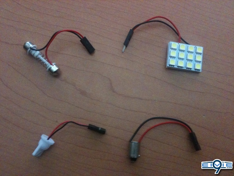
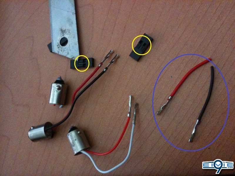
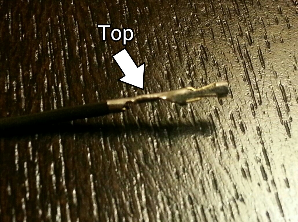
Step 1 – Pins
You should have received 3 adapters with the 12SMD LED. You will need all three adapters for this project and disregard the 12SMD LED board.
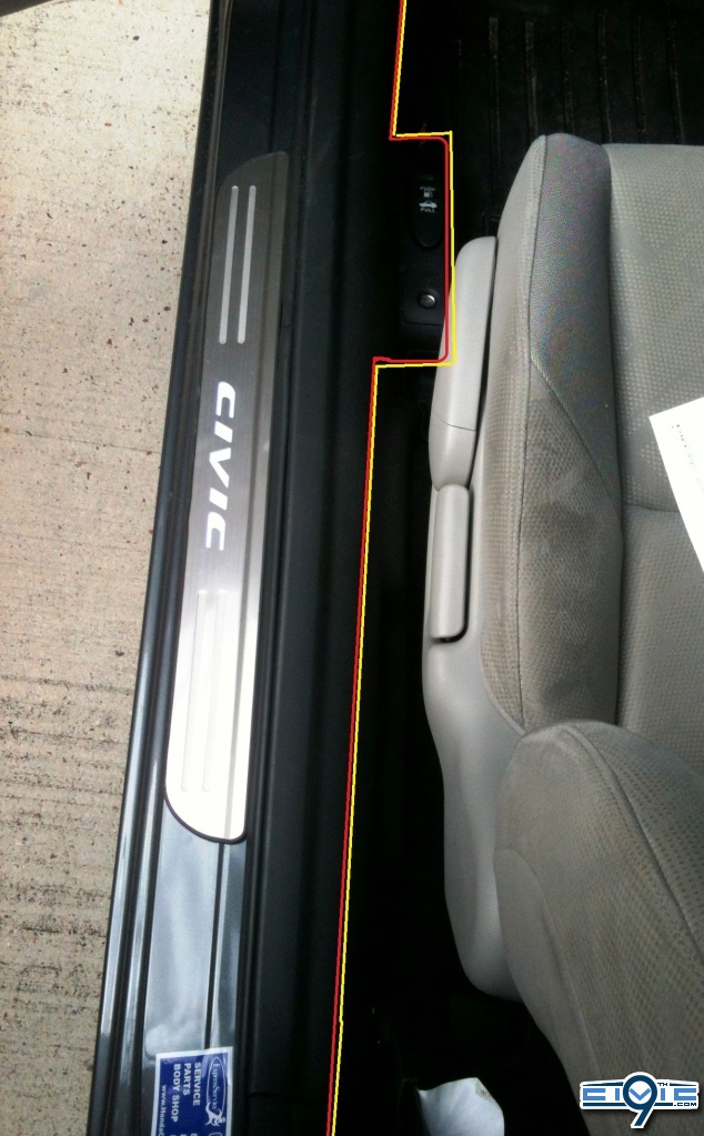
Using the wire cutter, cut the two adapters as exactly shown (yellow line).
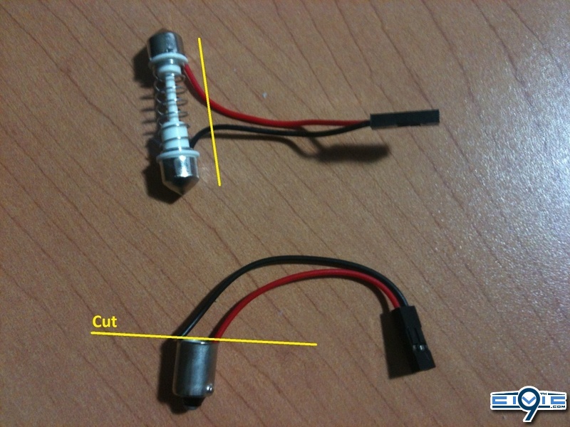
Take a small wedge (Jeweler Screwdriver or Utility knife) to unlock the pins of the two adapters from their socket (yellow circle). You should end up with two pairs of pins (circle blue) total of 4 pins.
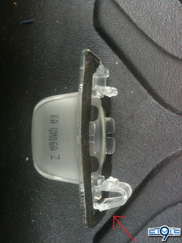
Step 2 – LED T10 Adapter
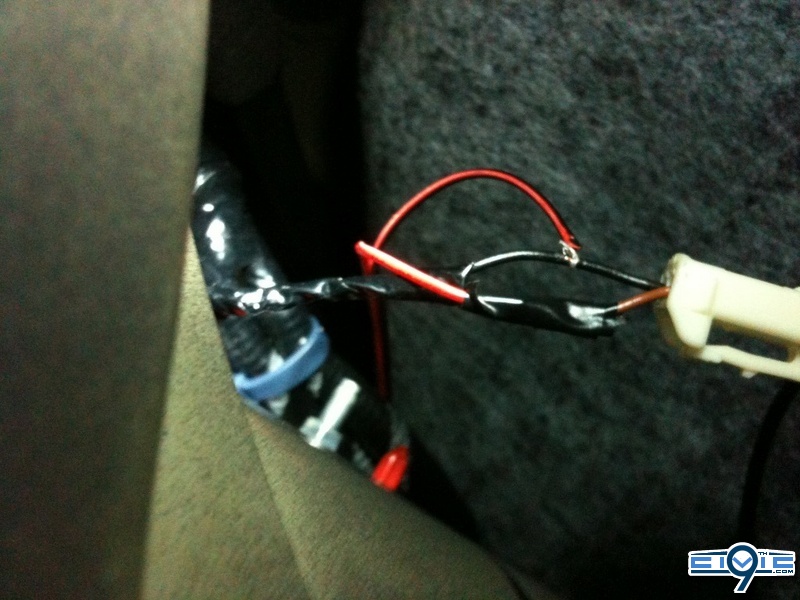
Using the wire cutter, cut the last adapter as exactly
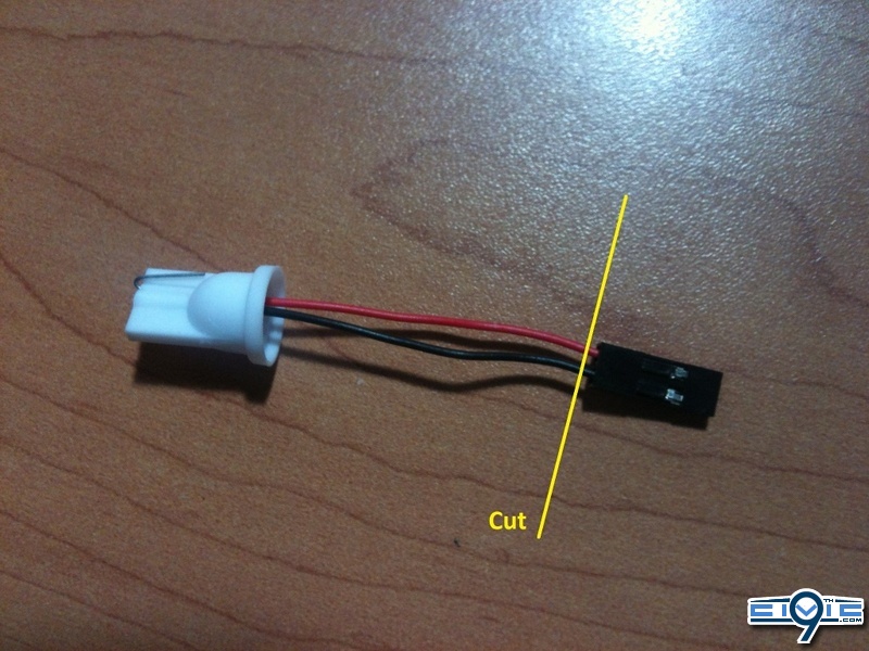
Connect this adapter to the end led wire of the camera as shown
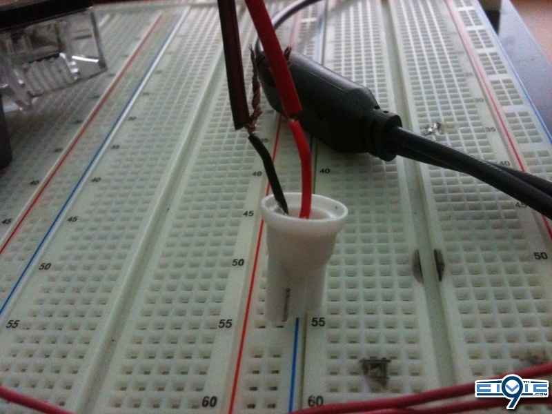
Cover the exposed wire ends with electrical tape. It should look as shown below.
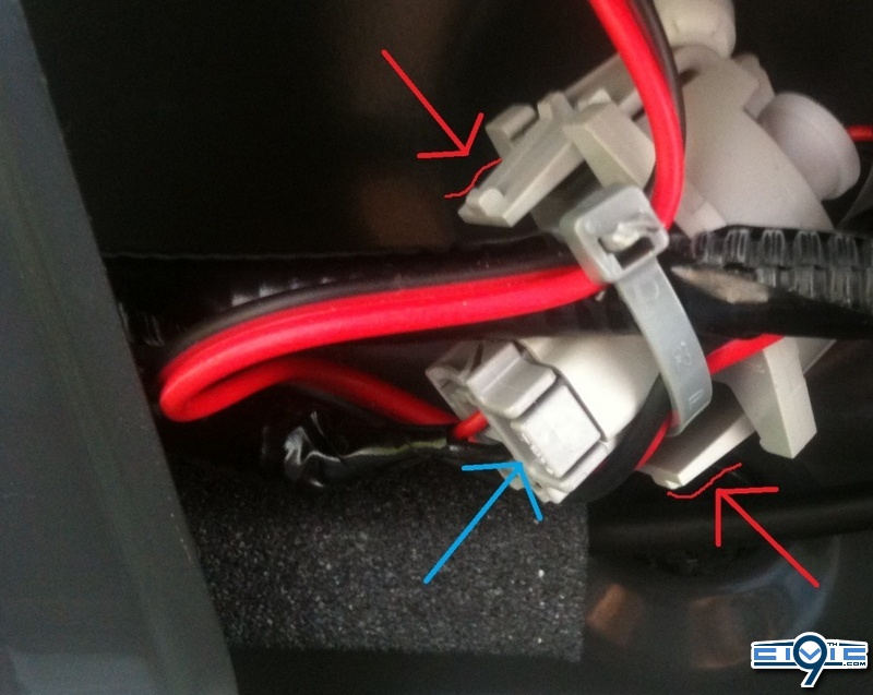
This will be plugged into the T10 socket in the trunk for your license plate LED

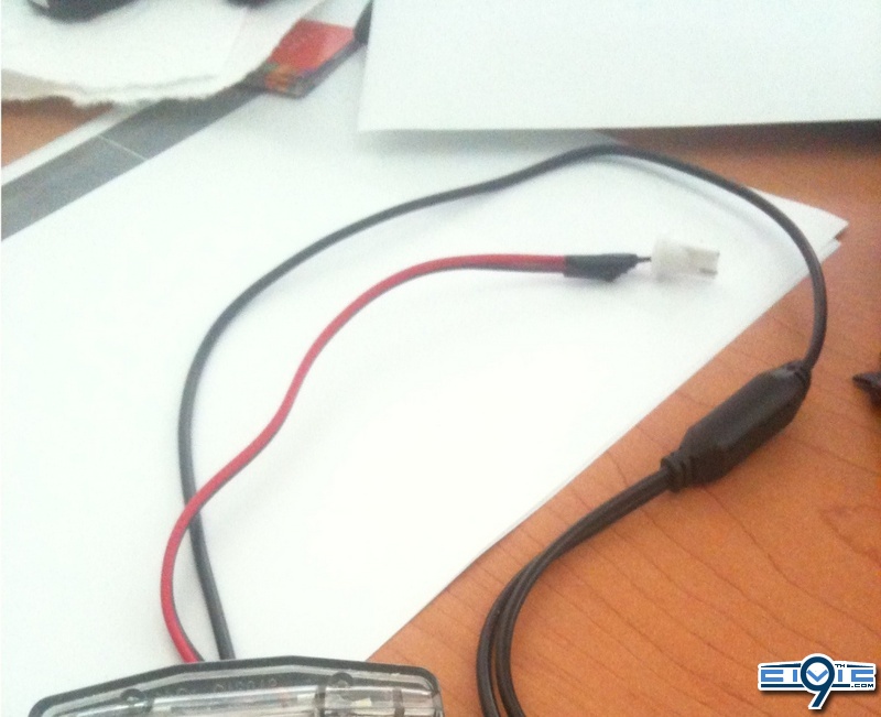
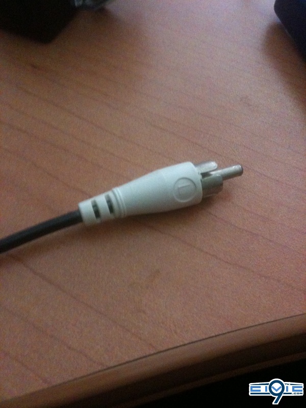
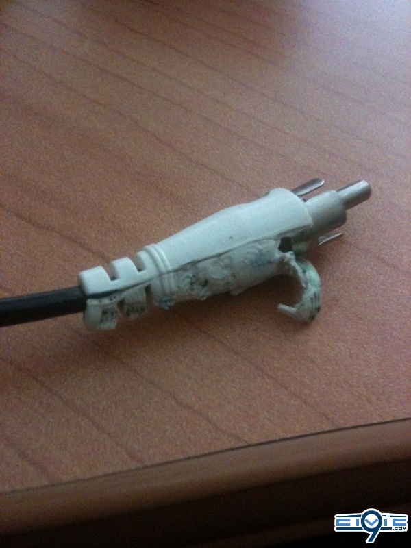
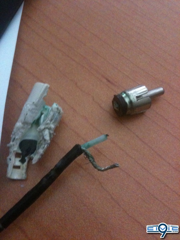
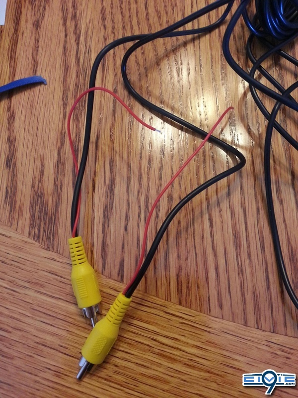
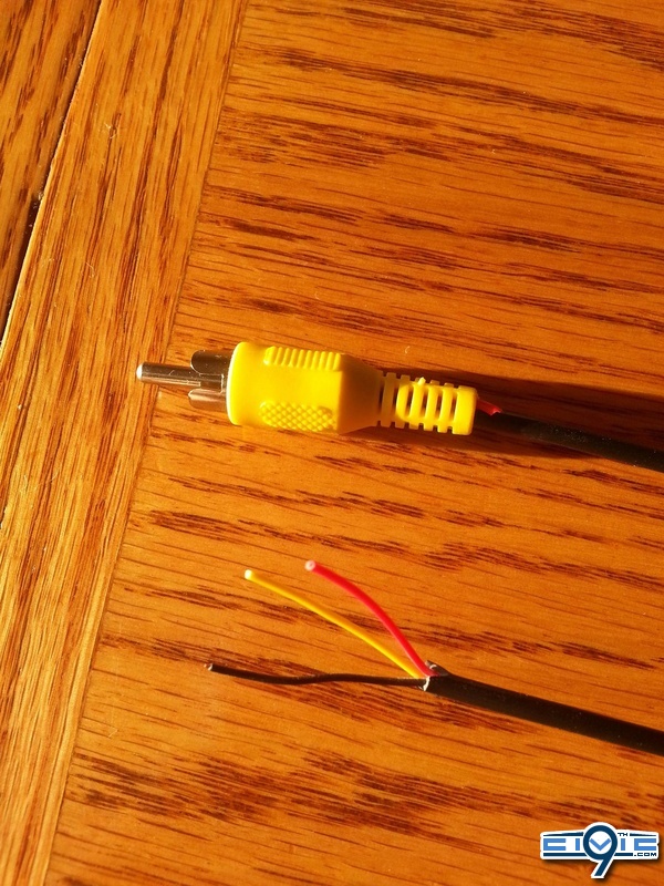
Step 3 – RCA Cable
You should have received a yellow extension RCA Cable with the camera. Using wire cutter and tear down one end of the cable (ignore the tiny red wire hanging out). I used a white RCA cable that was in my cable box. Your progression should look like the next following 3 pictures below.
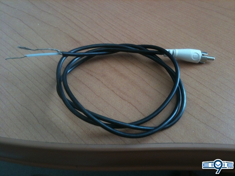
Your RCA cable ends should look like below.
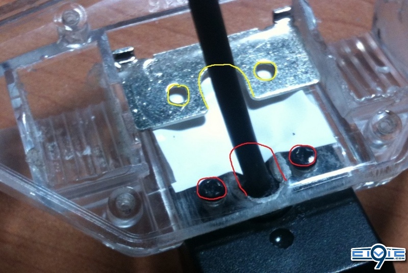
Step 4 – Camera
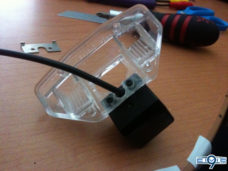
Using a Phillips screwdriver, unscrew the 4 screws in the back.
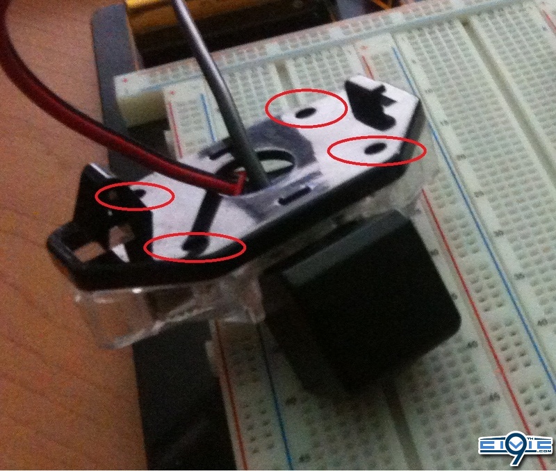
You will disassemble the camera taking everything out. Move the metal piece downward and use it as a template (outlined in yellow), mark the areas furthest to the bottom of the camera housing (outlined in red)
Note: The LED is held in by resin and is not necessary to be taken out. I personally wanted different LEDs in there.
Be very careful at this step, drill slowly and accurately. The plastic will crack or melt if done to fast. Take the power drill with a 1/16 bit and drill the small holes for the screws. After verifying the screws fit, take an adequate drill bit size and bore out an area for the camera wire can go through. Should look like below after you are done.
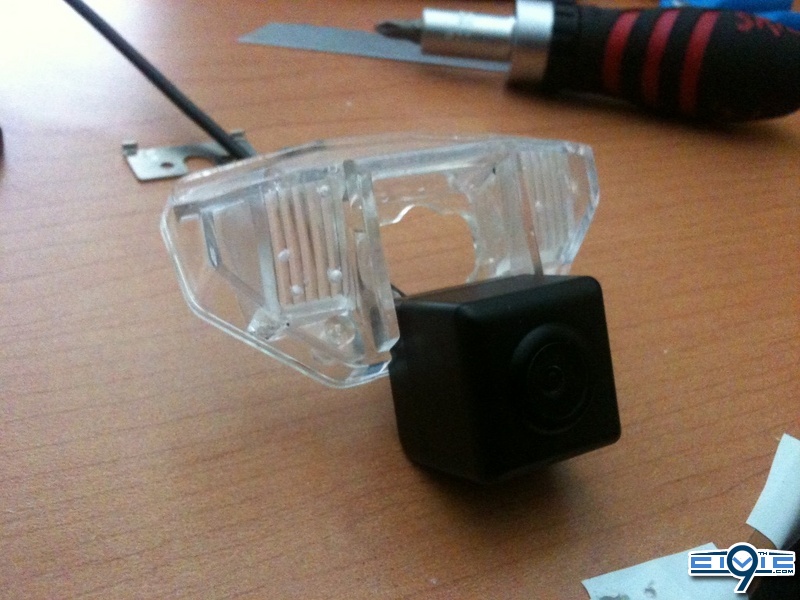
You can seal off the front hole with layers electrical tape. I did mine with vinyl tape and plasti dip to add some weather resist strength.
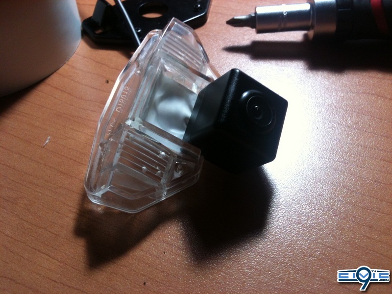
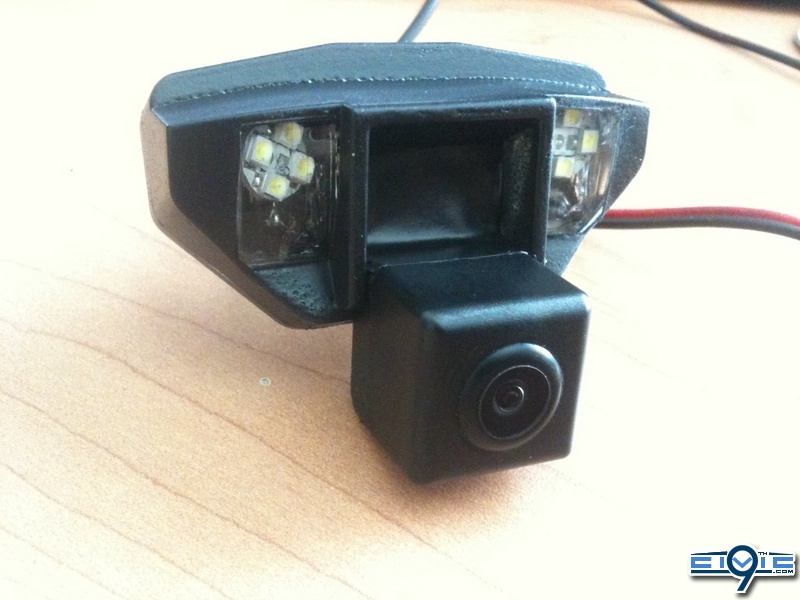
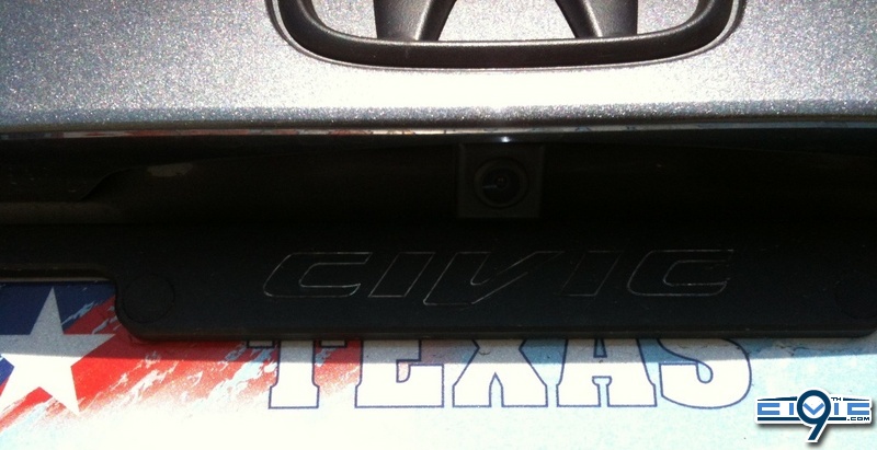
After the hole is covered to the way you like it. Reassemble everything back together and the camera should sit similar to this.
9thcivic.com may or may not endorse various DIY projects, all DIY projects are purely "at your own risk". If you are at all uncomfortable or inexperienced working on vehicles (especially electronics and mechanical), please reconsider doing the job yourself. It is possible on any DIY to damage your car, void your factory warranty, disable a safety feature, create a hazardous condition, or harm or even kill yourself or others. Examples would be the vehicle failing on you, getting an electric shock, or disabling an airbag etc.
Your dealer or mechanic, or professional audio shop may provide services (and a warranty) for any DIY job posted on these forums. Sometimes, it’s just better to pay to have it done.
FAQs
Q: Is this DIY for all civics?
A: This DIY is for civics with iMids without Navigation. (Need confirmation on SIs)
Q: Whats the difference between Non-Si and Si iMids?
A: The SI's iMid screen display an additional info screen which is not confirm on which connector input is used
Q: Does this camera that you link us fit a sedan?
A: Yes, it will fit both Sedan and Coupe.
Q: Where are the pins to connect?
A: The pins to order is under Project Parts. They will be in the Prep-Work Instruction.
Q: Will I need a soldering iron or solder anything?
A: No, there will not be any soldering needed.
Q: Do I need to take off the rear deck lid on my Civic Sedan to remove the light cover?
A: Yes you do, instructions are under Sedan Models Only. This does not relevant to Coupes.
Q: How much did this project cost?
A: Depends on how much of the tools you have already. Order the requiring Parts will be about $33.
Tools
Required:
- Black / Electrical Tape
- 20 Zip ties
- Wire cutter
- Utility Knife
- Medium Phillips Screwdriver
- Small / Jewelers Flat-head Screwdriver
- Trim Removing Tools
- Extra wire or tug wire
- Power Hand Drill
- Drill bits sizes 1/16 to 1/4
Recommended:
- Wire strippers
- Wire connectors (Marettes)
- Needle nose pliers
Project Parts
Required:
Reverse Camera -2012 Reverse CRV/CIVIC Back up Camera
Part Link - 7500K Xenon White LED CRV Fit 09 Civic Honda Car Mirror Rearview Camera P7512W | eBay
Cost: $19.00USD + Free Shipping
Shipping /Receiving Time: 7-15 business days
Comment(s): One of the issue I ran across as several other that when installed, the top of the camera view seems to cut off. So the linked one is one of the cheapest, has guide lines, and easiest to modify lower without getting to messy. There are several cameras on ebay that is similar to this one without guideline, whiter light, etc.
Note: When ordering, request 6000k LEDs
The original camera link is no longer available, but this seller has an active one with a similar model:
http://www.ebay.com/itm/Special-HONDA-CRV-FIT-2009-2012-CIVIC-Crosstour-Odyssey-Car-Backup-Camera-P7512L-/200884431596?pt=UK_In_Car_Technology&hash=item2ec5a52aec
Wire - 50ft 22 AWG Gauge Stranded Copper
Part Link - 50 ft 22 AWG Gauge Zip Wire Red Black Stranded Copper Power Ground | eBay
Cost: $9.92USD + Free Shipping
Shipping /Receiving Time: 3-7 business days
Comment(s): Any wire gauge from 20+/-2 (18-22) will work; Just make sure it is stranded to reduce wire heat and less surge. There is also plenty of cheaper one from overseas but I ordered from this seller several times.
Note:
Pins - White 12 SMD LED Car Interior Festoon Light Lamp Panel T10 Dome BA9S Adapter 12V
Part Link - White 12 SMD LED Car Interior Festoon Light Lamp Panel T10 Dome BA9S Adapter 12V | eBay
Cost: $2.49USD + Free Shipping
Shipping/Receiving Time: 7-15 business days
Comment(s): You will be taking apart the adapters for 4 of the pins
Note: You can use the dome adapter for the 12smd LED for rear dome lights.
Recommended:
Wire Tap – Posi-Tap
Part Link - Best Wire Tap Connector Posi Tap No Tools Strong Better Faster | eBay
Cost: $6.29USD + $6.00USD Shipping
Shipping /Receiving Time: 3-7 business days
Comment(s): This is not necessary to have but it will prevent you to cut or splice any wires so consider it as a fail-safe item. I recommend those who don’t work with wires often to purchase some sort of tap.
Note: Request the seller you want the red ones (18-24 gauged).
Note2: There are several different taps on ebay cheaper than this from $3.00USD - $7.00USD shipped. Just search wire tap and make sure it is red (18-24 gauged)
The wire taps (above) are not available, but I found a different style here (they also sell the 22 AWG dual conductor stranded wire):
http://www.lowes.com/pd_450934-37672-50054_0__?productId=4415289&Ntt=non splice wire connector&pl=1¤tURL=?Ntt=non+splice+wire+connector&facetInfo=
Prep Work
Step 1 – Pins
You should have received 3 adapters with the 12SMD LED. You will need all three adapters for this project and disregard the 12SMD LED board.
Using the wire cutter, cut the two adapters as exactly shown (yellow line).
Take a small wedge (Jeweler Screwdriver or Utility knife) to unlock the pins of the two adapters from their socket (yellow circle). You should end up with two pairs of pins (circle blue) total of 4 pins.
Step 2 – LED T10 Adapter
Using the wire cutter, cut the last adapter as exactly
Connect this adapter to the end led wire of the camera as shown
Cover the exposed wire ends with electrical tape. It should look as shown below.
This will be plugged into the T10 socket in the trunk for your license plate LED
Step 3 – RCA Cable
You should have received a yellow extension RCA Cable with the camera. Using wire cutter and tear down one end of the cable (ignore the tiny red wire hanging out). I used a white RCA cable that was in my cable box. Your progression should look like the next following 3 pictures below.
Your RCA cable ends should look like below.
Step 4 – Camera
Using a Phillips screwdriver, unscrew the 4 screws in the back.
You will disassemble the camera taking everything out. Move the metal piece downward and use it as a template (outlined in yellow), mark the areas furthest to the bottom of the camera housing (outlined in red)
Note: The LED is held in by resin and is not necessary to be taken out. I personally wanted different LEDs in there.
Be very careful at this step, drill slowly and accurately. The plastic will crack or melt if done to fast. Take the power drill with a 1/16 bit and drill the small holes for the screws. After verifying the screws fit, take an adequate drill bit size and bore out an area for the camera wire can go through. Should look like below after you are done.

You can seal off the front hole with layers electrical tape. I did mine with vinyl tape and plasti dip to add some weather resist strength.
After the hole is covered to the way you like it. Reassemble everything back together and the camera should sit similar to this.
Last edited by a moderator:


")

