- Staff
- #381
- 57,226
- 24,355
Hopefully it works out for you
Follow along with the video below to see how to install our site as a web app on your home screen.
Note: This feature may not be available in some browsers.
A bought this universal kit (camera and wire).

http://www.ebay.com/itm/232266611574
I hope it mounts better than the plate light location that required mods to improve the view.
The better kits (I saw only a few) include a harness which appears to only eliminate the need for the three pins but ~$160.

http://www.ebay.com/itm/2012-2013-H...ash=item33a696ddaa:g:27AAAOSwys5WULKm&vxp=mtr
http://www.ebay.com/itm/171979508848I received the kit today. The bad news is that instead of two nuts to adjust the camera mounting offset, the camera has only one nut. Not sure if I need two nuts as maybe a snug fit will work. Hopefully I can mount it so it will have a clear view. We will see.
The good news is that the long video cable (yellow RCA plugs) also incorporates a red wire so that will carry power when reversing. So this 3 wire cable will run from rear to the front dash carrying video signal (center of plug), ground/shielding (outer), and power when in reverse without having to add another wire. This makes my happy as adding wire to a multi-wire cable looks like a bad hack.
I ordered this for the three female pins I will need.

http://www.ebay.com/itm/171979508848
This kit has more female connector pins than needed (need 3) but I want to install the center dome bulb.
I will install in a few days.
Having same problem as other user where the video feed can be seen in the service menu when the car is in reverse but the imid doesn't automatically switch over when the car goes into reverse. Again, the feed is only seen thru the special menu when the car is in reverse.
I don't know if anyone would have wiring diagrams on the crv forums? If not, you may have to get a wiring diagram from Honda. They charge $10/day to pull stuff online.Can someone please help me. I'm having problem wiring the new camera to make it work. The stock camera from factory has 4 wires and connected using 6 pin connector. I'm having problem finding a wiring diagram for my new camera that came from 2014 CRV.
Factory Connector 6 Pin
View attachment 56121
New Camera from CRV
View attachment 56122
Dash Removal Instructions
OrbisTheory - 2012 Honda Civic SI - How To Remove The Dashboard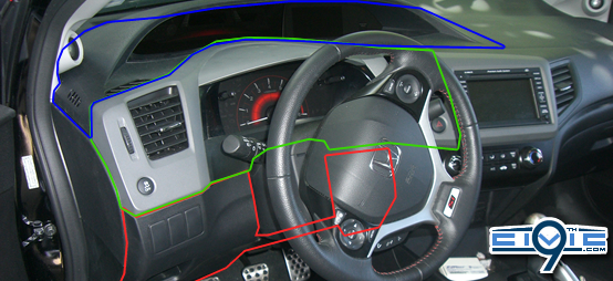
The entire dashboard comes apart in three separate pieces (highlighted in image). The lower section (red) is held on entirely with clips. The middle section (green) is also held on entirely with clips, but there are two connectors (or possible more with other models) that must be disconnected. The third, upper section (blue) requires the removal of three screws and then can be unclipped.
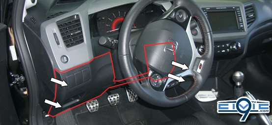
I would recommend starting along the edges marked with arrows. Particularly, the left hand side seems the easiest to pull the clips out. The pull takes some getting used to - but it literally requires pulling on the section of dash until it breaks out of the clips. In all likelihood, some will break during this process. I wouldn't worry too much about it - there are so many (which can be moved around, too) that the panel should stay fairly tight...even if you lost a few clips in the process.
When pulling the dash off, I would HIGHLY recommend that you don't use absolute brute force. Try grabbing parts of the panel and wiggling it, bending it some, or otherwise "working" the clips out.
The clips for this piece are entirely around the edges. The most difficult ones, I found, are the upper corners on either side of the steering column. You may need to reach up under the panel and try pushing/wiggling back there.
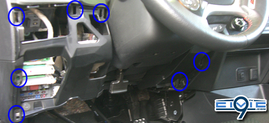
You can see in the image above some of the clip positions for the lower section.
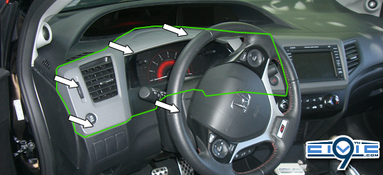
The middle section is also entirely clips, except for two wire connectors on each side. I'd recommend starting on the left side and working your way across the top and the bottom. The clips on the right (near the nav in the image) can be tough. Remember; try not to just pull with brute force. Try to "work" the clips out. Note that both wire connectors are in with clips, but are fairly easy to remove. Push the tab and pull.
Above shows SOME of the clip positions (enough to get started).
The upper section is the most difficult to remove. The right side has many clips in a relatively small location, and it is difficult to get a grip in this area. First, unscrew the three screws marked below. You do not need to remove any of the screws holding the tachometer. Only the three marked below.
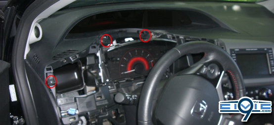
I would HIGHLY recommend putting tape on the bottom corner of the driver's side tweeter. The fit to get the upper piece out is very tight (and consequently, getting it back in). Pay attention when removing it to see the easiest way to swing the piece out. You're going to want to put it back in the same way.
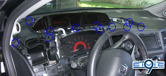
Per usual, not every clip has been marked above. Note that there are clips directly at the bottom of the IMID and speedometer. The right side is difficult to remove as there are many clips close to each other and no good grip spot. Also, and this is important, there are clips along the top edge near the windshield. You may need to work between the bottom and the clips in this area. The clips aren't necessarily angled up, so the direction of pull is closer to pulling straight out, away from the dash components.
Front Installation
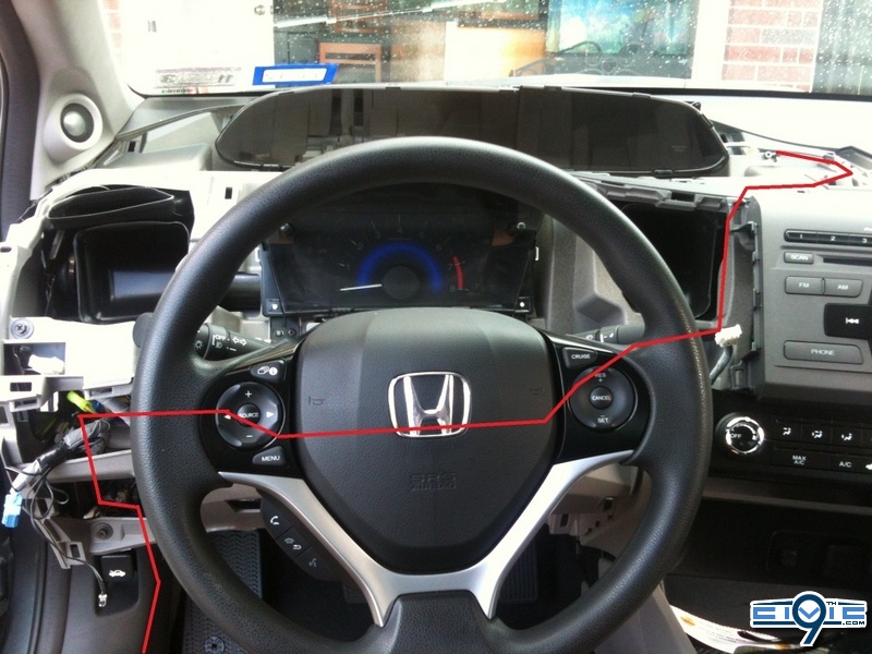
After the dash has been removed, continue to run the wires upwards and through the dash (wire in red)
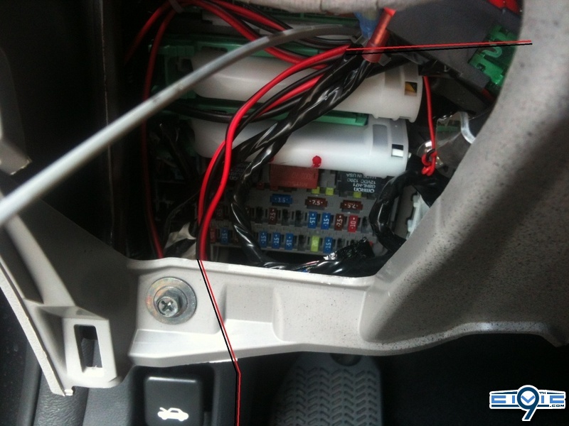
Continue to run the wires it behind the steering wheel but make sure that the wires don’t hinder the steering wheel from making adjustments in the future. Pull it through and upwards as the picture show (red lines)
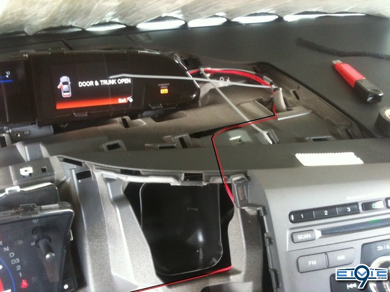
Over all view the wires should have ran through the dash something like this. Don’t forget to zip tie and secure the wires.
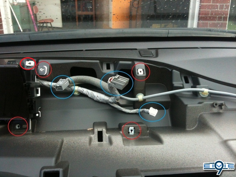
Now that you have your wires set. Remove the iMid from the dash by unscrewing 5 screws as shown (red circle) and unclipping 3 connectors (blue circle)
After your iMid is removed, look at the 32Ppin connector and you will see a black piece on the connector. Take a tiny screwdriver and wedge it in the grove to pop it out. It does not come off so don’t try to pull it out. Take three pins you made before and insert them into the 32pin connector pin slow 14 18 19, making sure to keep the pin orientated correctly, as shown in the next picture.
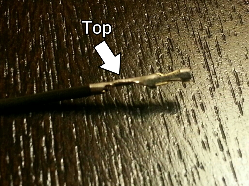
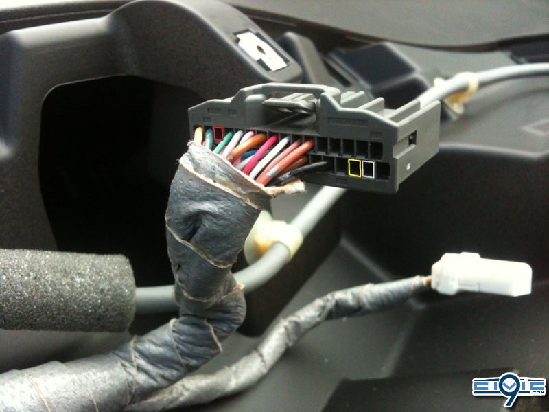
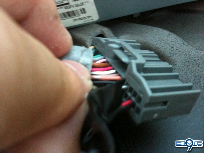
The pin’s openings are going to be seen where it is marked below. Once you see the pins on all three, you can push back the pin lock to secure them. You can align them with a paperclip if needed.
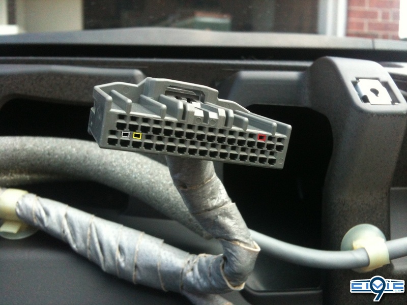
Reconnect the 32P Connector and put into reverse to test. If it doesn’t come on, double check one of the starting with the pin seated correctly and not being pushed back when connected, then the cable connection from the camera then the spliced/tapped wire connection. If that of this is perfect then you may have popped a fuse but it is highly unlikely if you use tappers.
Double check all wires that they are not exposed and are secured. Reverse instruction and reinstall the iMid, dash panel, trunk liner, etc.
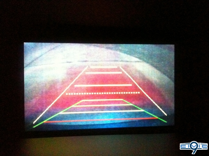
Yellow Grid line Adjustment
This should work on all 9th Gen Civics with the i-MID display...
Press the MENU button on the steering wheel to access the vehicle menu:
Then press and hold SELECT and MENU at the same time for approx 20 seconds. You should then get the Service Diag Menu
Adjust Reversing Camera gridlines.
Keep asking questions as I will add them to the FAQ for future references. I hope this was a decent DIY, if so I will do more in the future.
AFTER SPENDING NEARLY 100 HOURS TO WORK AND PERFECT EVERYTHING IN THIS DIY, PLEASE THANK ADEXTERNAL AND MANY OTHERS FOR MAKING THIS A TEAM EFFORT!!!
I don't know if anyone would have wiring diagrams on the crv forums? If not, you may have to get a wiring diagram from Honda. They charge $10/day to pull stuff online.
https://techinfo.honda.com/rjanisis/logon.aspx
http://9thcivic.com/forum/threads/a...rse-backup-camera-diy.6538/page-2#post-131909Why won't this work with navigation equipped cars? I don't understand what the big difference between navigation and non navigation, they look the same to me and with navigation you can hit the menu button then hold menu and source for 20 seconds and a menu with the backup camera comes up and you can see yellow lines with a black background.
Thanks, I assume this is for power? Is there one for reverse singal as well?Fuse 23 is an open slot and works when the car is turned on.
2014 has a stock backup cam. The 2012's didn'tHi did anyone install in a 2014 and get it working? im having a issue where when i put in reverse it does nothing but it diagnostic mode i can see the video. i played with pin 14 for hours so im sure its not that
thanks
