DIY ADExternal's 2012 Honda Civic Reverse Backup Camera DIY

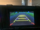
Did anyone order that kind of camera? I wonder if it will work in European Civic IX 2012, 4D Sedan, 1.8, Comfort Edition. Looks like it should work but maybe you know some other, more interesting types of cameras that work with the i-mid display?
BTW, where that camera should be placed? Originally it's just below Honda emblem or I have to place camera just a litlle bit of right or left?

aliexpress.com/item/32801251825.html?spm=a2g0o.productlist.0.0.6856525aEf4ECA&algo_pvid=9120c508-97f6-45b8-bfa8-740aa05087fc&algo_expid=9120c508-97f6-45b8-bfa8-740aa05087fc-6&btsid=0b0a0ac215819542488074118e51ae&ws_ab_test=searchweb0_0,searchweb201602_,searchweb201603_
 
Last edited:
I have a 2012 Civic Si Sedan. I have everything setup and the wires pinned, but when I put the car in reverse nothing happens… I have to go to the IMID menu to put the car in reverse to view the camera. HELP
 

Attachments

  • CA3258AB-6D0C-4136-9665-53E1CB9716B8.jpeg
    CA3258AB-6D0C-4136-9665-53E1CB9716B8.jpeg
    1.4 MB · Views: 5
  • 235DEF7E-D494-4558-B8C3-2E7FC384FA17.jpeg
    235DEF7E-D494-4558-B8C3-2E7FC384FA17.jpeg
    1.6 MB · Views: 5
I have a 2012 Civic Si Sedan. I have everything setup and the wires pinned, but when I put the car in reverse nothing happens… I have to go to the IMID menu to put the car in reverse to view the camera. HELP
I see you asked someone about Navi. Do you have Navi?

If you don’t have Navi, everyone has said that pin 14 is the issue for it showing in the diag menu, but not when it's in reverse.
 
I see you asked someone about Navi. Do you have Navi?

If you don’t have Navi, everyone has said that pin 14 is the issue for it showing in the diag menu, but not when it's in reverse.
I do have nav and camera is only working in the diag menu, not sure what to do
 
I do have nav and camera is only working in the diag menu, not sure what to do
as stated in the original post, this diy was for non-nav owners. The setup is different for users with nav, and I've yet to see anyone be able to do it successfully with nav. It was dissected quite a bit in this thread, but no luck
 
as stated in the original post, this diy was for non-nav owners. The setup is different for users with nav, and I've yet to see anyone be able to do it successfully with nav. It was dissected quite a bit in this thread, but no luck
Would it be possible to wire the camera to the factory nav instead of the IMID?
 
stuck at the same point as @Blimpcity at comment #181 and @Fuzz at comment #382
on reverse Signal nothing happen. but in camera diagnostic mode camera works only when car is in reverse

troubleshooted every connection all pin 14.18 and 19 are intact and functioning properly
tried with additional wires as suggested by @Fuzz at comment #383

nothing worked for me

on other forums many members faces the same problem but I have not find any solution to it
thanking all in anticipation
Your IP address is showing you’re from outside North America. I don’t know if this is correct, but if you are outside North America that is a problem. The guide here is for civics found in Canada and the US markets. Other countries actually have a different civic vehicles than what we have here. Wiring, engines, radios, and vehicle options/trims are even different between countries.
 
Your IP address is showing you’re from outside North America. I don’t know if this is correct, but if you are outside North America that is a problem. The guide here is for civics found in Canada and the US markets. Other countries actually have a different civic vehicles than what we have here. Wiring, engines, radios, and vehicle options/trims are even different between countries.
That does make sense Webby. However, I never figured out how to get it to work on my USDM Si. I stopped trying to figure it out after my trouble shooting efforts failed. On the positive side, my 2021 Type R has a factory backup camera so you have that...
 
That does make sense Webby. However, I never figured out how to get it to work on my USDM Si. I stopped trying to figure it out after my trouble shooting efforts failed. On the positive side, my 2021 Type R has a factory backup camera so you have that...
I cannot find a great picture, but Pakistan shows a pretty large lcd display for the radio from what I’ve seen (where this user is potentially from). I know people here with navigation wanted to get the reverse camera working, but it was also a nightmare for those individuals. See below for the Pakistan model.

E226B640-5A06-42D2-9615-42F9A2C8FE20.jpeg
 
Thanks for responding, many civic users of my country have already successfully installed said camera on iMid
It works flawlessly
However, i still haven’t figured it out why its not working for me
 
I’m really unclear with opening the RCA cable. When I opened up my RCA cable, there’s a red, green, and black wire inside it. Which one is it that I’m supposed to connect to Pin #19?
 
I’m really unclear with opening the RCA cable. When I opened up my RCA cable, there’s a red, green, and black wire inside it. Which one is it that I’m supposed to connect to Pin #19?
I would assume your green wire is the video feed (yellow wire) mentioned in the diy
 
I would assume your green wire is the video feed (yellow wire) mentioned in the diy
So the green wire only goes to Pin #19? I ran separate power (red) and ground (black) wires that are tapped into reverse lights. Was I supposed to just use the red and black wires contained within the RCA cable?
 
So the green wire only goes to Pin #19? I ran separate power (red) and ground (black) wires that are tapped into reverse lights. Was I supposed to just use the red and black wires contained within the RCA cable?
1664929888974.jpeg

I’ve not done the diy, but he shows yellow to pin 19 (I’m guessing your green wire), red wire to pin 14 and black wire to pin 18.
 
View attachment 65295

I’ve not done the diy, but he shows yellow to pin 19 (I’m guessing your green wire), red wire to pin 14 and black wire to pin 18.
My original interpretation was that the “yellow” wire in the diagram was the yellow RCA cable in its entirety. And the “red” and “black” were additional 18-22ga wires, since he lists the red and black wire in his parts list. He doesn’t mention just run the RCA cable, then break it open to find all the wires you need.

The pictures of him cutting back the white RCA cable look different than what I have. But then there’s a random picture of a yellow RCA cable with three wires exposed, similar to what I have? Hard to figure out what’s going on here.
 
do you have a picture of your rca cable ends you cut, or what it looks like currently? He used a white cable for his, because it was a spare wire he had from his cable box. He shows it opened with 2 wires, and then he shows the yellow rca that came with the camera cut open that had the extra red wire in it. He says ignore the red wire in that yellow rca cable. I guess he just wanted to show both cables cut open for the diy.


===============================
===============================

Step 3 – RCA Cable
tear down one end of the cable (ignore the tiny red wire hanging out). I used a white RCA cable that was in my cable box).

Your RCA cable ends should look like below.


IMG_0260.sized.jpg


Then he shows the yellow rca that came with the camera and how it looks when he cuts it open -

SG0ALdl.sized.jpeg


ITPtqoT.sized.jpeg


And the “red” and “black” were additional 18-22ga wires,
yes, hopefully someone else will chime in that's done this, but I would assume those are the new 22gauge wires he mentioned to buy. You'd only be using the "yellow" wire from the rca to pin a19 if I'm understanding correctly. The red/black wires would be new wires he mentions to buy going to the 14/18 pins per his diagram. Someone please chime in if this is incorrect. I'd like to see your rca cable cut and what the ends look like though.
 
do you have a picture of your rca cable ends you cut, or what it looks like currently? He used a white cable for his, because it was a spare wire he had from his cable box. He shows it opened with 2 wires, and then he shows the yellow rca that came with the camera cut open that had the extra red wire in it. He says ignore the red wire in that yellow rca cable. I guess he just wanted to show both cables cut open for the diy.


===============================
===============================

Step 3 – RCA Cable
tear down one end of the cable (ignore the tiny red wire hanging out). I used a white RCA cable that was in my cable box).

Your RCA cable ends should look like below.


IMG_0260.sized.jpg


Then he shows the yellow rca that came with the camera and how it looks when he cuts it open -

SG0ALdl.sized.jpeg


yes, hopefully someone else will chime in that's done this, but I would assume those are the new 22gauge wires he mentioned to buy. You'd only be using the "yellow" wire from the rca to pin a19 if I'm understanding correctly. The red/black wires would be new wires he mentions to buy going to the 14/18 pins per his diagram. Someone please chime in if this is incorrect. I'd like to see your rca cable cut and what the ends look like though.
do you have a picture of your rca cable ends you cut, or what it looks like currently? He used a white cable for his, because it was a spare wire he had from his cable box. He shows it opened with 2 wires, and then he shows the yellow rca that came with the camera cut open that had the extra red wire in it. He says ignore the red wire in that yellow rca cable. I guess he just wanted to show both cables cut open for the diy.


===============================
===============================

Step 3 – RCA Cable
tear down one end of the cable (ignore the tiny red wire hanging out). I used a white RCA cable that was in my cable box).

Your RCA cable ends should look like below.


IMG_0260.sized.jpg


Then he shows the yellow rca that came with the camera and how it looks when he cuts it open -

SG0ALdl.sized.jpeg


ITPtqoT.sized.jpeg


yes, hopefully someone else will chime in that's done this, but I would assume those are the new 22gauge wires he mentioned to buy. You'd only be using the "yellow" wire from the rca to pin a19 if I'm understanding correctly. The red/black wires would be new wires he mentions to buy going to the 14/18 pins per his diagram. Someone please chime in if this is incorrect. I'd like to see your rca cable cut and what the ends look like though.
I’m not in a place where I can take pictures of my RCA cable at the moment. But my cable looks just like this picture, except my yellow wire is actually green.

1664964603220.png
 
So I hooked the yellow (actually green in my case) wire from my RCA cable to Pin #19, and the red and black wires inside the RCA cable are hooked to nothing. When I put car in reverse, it switches to reverse camera, but the video feed looks like crap. Don’t know if it’s because the camera is garbage, or if my red and black wires within the RCA cable need to be hooked to something.

I took a picture of my video feed, and interestingly, my phone makes the video feed look way better than it does in real life. In reality, the feed is real dark, and so far my backup camera is unusable due to the poor quality feed.
 

Attachments

  • FD1DD3A7-900A-428A-8DDC-9D58DAAF96ED.jpeg
    FD1DD3A7-900A-428A-8DDC-9D58DAAF96ED.jpeg
    3.1 MB · Views: 4
Back
Top